
Glove box specifications tend to describe the chamber in loving detail and treat the gas-handling hardware as plumbing to be settled later. For anyone working with air-sensitive materials, that order is backwards. The valves that gate a vacuum line decide how gently, how repeatably, and how predictably a box moves through a pump-and-backfill cycle, and a poorly chosen one shows up as slow transfers, drifting pressure, or a sequence that nobody can explain afterwards.
A pneumatic vacuum baffle valve is one of those gatekeepers. It sits in the vacuum train, the path from a transfer chamber, an antechamber, or the main volume to a pump, and it determines when gas may move and when the volumes on either side are isolated from one another. This article treats the accessory on its own terms: the mechanism, the duties it can and cannot perform, the choices that matter when sizing it, and the compatibility questions worth settling before it is ordered for a particular system. Vacuum-type stainless steel boxes from the same product family, such as the GBV-3 stainless steel vacuum glove box, appear here as background context rather than as a guaranteed pairing.
What a Pneumatic Vacuum Baffle Valve Actually Does
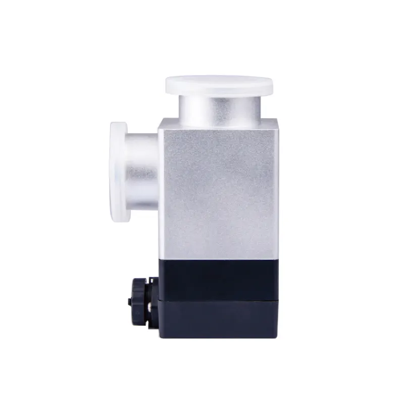
A baffle valve is built around a pivoting disc. When open, the disc swings clear of the bore and leaves an aperture close to the full port diameter; when closed, it presses against a sealing face and closes the line. The pneumatic qualifier describes the actuator: compressed air drives a piston or diaphragm that strokes the disc, instead of a handwheel, a lever, or an electric motor. The accessory shown on the pneumatic vacuum baffle valve page belongs to this family of flow-gating devices, and the questions below apply to any valve of this class.
Isolation and throttling are different duties
Because the disc moves out of the flow path, baffle geometry is aimed at conductance, meaning low resistance in the open state. That makes it a good shutoff element where a line should be wide open or firmly closed. It is a poor choice for fine regulation. If a process needs gas admitted slowly and repeatably, a metering valve with a characterised trim is the better instrument; stroke-to-flow behaviour in a baffle is nonlinear and can shift with seal friction and supply pressure, so treating one as a precision throttle is a misapplication. The first decision, then, is which duty is actually required: a high-conductance shutoff, a controllable restriction, or both in series at different points in the train.
Why pneumatic actuation changes the workflow
Manual valves need a hand at the valve, which on a glove box often means reaching into the antechamber or the space around the chamber. That is awkward at best, and disruptive if the chamber is already conditioned. Pneumatic actuation moves the action into the control cabinet: a pilot solenoid admits air to the actuator, and the sequence lives in a PLC, a timer relay, or a simple interlock chain. Three consequences follow.
First, the valve can be interlocked with the pump and with the backfill valve so that evacuation and refill cannot overlap. Second, cycle timing becomes repeatable, which matters whenever runs are compared with one another or a process is transferred between operators. Third, the fail position becomes a deliberate design decision rather than an accident: a spring-return valve that closes on air loss leaves the system in a defined state, while a double-acting valve holds its last position until the control system moves it. Neither behaviour is universally right, and the choice depends on what the valve isolates and what happens downstream if it moves.
The actuator is also a maintenance surface
Pneumatic actuators introduce failure modes that have nothing to do with the vacuum side. Water and oil carried in a compressed-air line attack piston seals; a supply that sags below the actuator's requirement can leave the disc only partly stroked, producing a restriction that mimics a tired pump rather than a valve problem. Air preparation, filter maintenance, and a periodic pressure check belong in the service routine alongside the usual leak checks. It helps to record the supply pressure at commissioning, because a number on a gauge only becomes useful when there is a baseline to compare it against.
Where the Valve Sits in a Glove Box Vacuum Train
The vacuum train runs from the volume to be evacuated to the pump that does the work. In a box with a transfer chamber the path is usually short: chamber, valve, line, pump, sometimes with a second valve near the pump so that the pump can be isolated and vented on its own. Each position imposes a different duty, and the same valve model is rarely ideal for all of them.
Transfer chamber and antechamber lines
Bringing a sample into a vacuum-type box follows a familiar sequence: open the outer door, load the sample, close the door, evacuate the small chamber, refill it with the working gas, then open the inner door. The valve on that chamber's pump line strokes on every single transfer. Cycle count, seat wear, and stroke repeatability therefore weigh more heavily here than in a duty where a valve is operated a few times a month. If the process involves loose powder inside the transfer chamber, the way the valve opens also matters. A rapid full-aperture opening produces a surge of gas that can lift fine particles and carry them towards the seat or the pump, so actuation speed and the surrounding geometry deserve the same attention as the vacuum specification itself.
Pump isolation and shared roughing lines
Another common placement is at the pump inlet, so that a single pump can be isolated from the system during idle periods or switched between two chambers. Sharing one pump across two chambers with two valves is an economical arrangement, but it creates a sequencing requirement: both valves must not be open at the same time unless the pressures on either side are compatible, and the control scheme has to make that condition impossible rather than merely unlikely. A position switch on each valve, or a documented interlock in the controller, is what converts the intention into a property of the system.
What the valve is not
It is worth stating the boundaries plainly, because accessory lists are often read quickly. A baffle valve does not create vacuum, purify gas, or measure anything. It does not remove moisture or oxygen; in a vacuum-type box that is achieved by evacuation and inert-gas replacement, and in a circulating system by a purification column. It is not a particulate filter. HEPA filtration addresses a different problem in a different location, and it does not reduce water, oxygen, or solvent vapour. It is not an analyser: an oxygen or moisture instrument measures the atmosphere rather than changing it. It is not a solvent adsorber either, and a solvent adsorber is not a substitute for water and oxygen removal. If a requirement list gives atmosphere control as the reason for buying a baffle valve, the requirement has been misread. The valve controls flow; chemistry is handled elsewhere in the system.
Aperture, Conductance, and Sealing: Reading the Baffle's Real Limits
Conductance is a property of the whole path
The width of the valve bore is only one contribution to how fast a chamber empties. Flexible bellows hoses, elbows, long straight runs, the port geometry of the chamber, and the pump inlet all add resistance in series with the valve. A generously sized valve installed behind a narrow hose behaves like a small valve, and replacing it will change very little. The useful exercise is to compare the valve's stated conductance with the conductance of everything else in the path and with the pump's pumping speed across the pressure range of interest. Whichever element has the lowest conductance sets the pace; that is where money is best spent.
Every closed valve is a seal in contact with the process gas
In a glove box the gas passing a valve may carry solvent vapour, traces of oxygen and moisture, and, in powder work, fine particulate. Seat materials are chosen for compatibility with those exposures. An elastomer that swells in a solvent or hardens after repeated cycling will eventually pass gas, and the first sign is usually a slow pressure rise after isolation rather than an obvious failure. Ask which seal material is fitted, what media it is intended for, and whether an alternative is offered for solvent-heavy or high-purity duties. Where particulate is expected, consider whether the seat and the disc edge can trap particles, and whether the valve can be cleaned or its seal replaced without discarding the whole body.
Baffle geometry compared with other valve types
Gate, butterfly, and angle valves all do similar work with different trade-offs. A gate valve offers a straight-through path and low resistance, but it needs more travel and often more space. A butterfly valve is compact and quick, though the disc remains in the flow path even when open, which adds some resistance. A baffle valve typically combines a swing motion with a compact body, which is convenient around a glove box where clearance for an actuator is often the binding constraint. The choice is rarely about a single number; it is about which compromise fits the space, the flange standard, and the frequency of operation in that particular line.
Actuation details that show up later
Supply pressure range, single-acting versus double-acting design, the presence of a position indicator or switch, and the expected cycling behaviour are specification items that determine how the valve fits into a sequence. A position switch is not a luxury on a valve that must be proven closed before a backfill begins. Without one, the control system is inferring state from the command it sent, which is not the same thing as knowing what the disc is doing.
Matching the Valve to the Pump, the Chamber, and the Controls
The pump sets the ceiling; the valve sets the path
No valve can compensate for an undersized pump, and no pump can compensate for a valve that opens onto a restriction. The two are selected as a pair against the chamber volume and the target pressure, and the pairing should be justified with data rather than with intuition. Where the sample is delicate, a loose powder, a fragile substrate, or a thin film, the transient matters as much as the endpoint, because the moment of opening can produce the highest instantaneous flow in the entire cycle. Slower actuation, a staged opening, or an intentional restriction upstream can reduce that surge without lengthening the overall cycle much, but the choice should be made deliberately rather than inherited from whatever valve happened to be available.
Control signals, interlocks, and the sequence
Pneumatic actuation implies a pilot solenoid and therefore a signal. Before ordering, write down the coil voltage, whether the pilot is mounted on the valve or remotely, whether position feedback is required, and how the valve will be interlocked with the backfill valve, the door switches, and the pump. The exercise is dull, and it is the single most reliable way to discover a missing requirement before the hardware arrives. A valve that is mechanically correct but electrically incompatible with the existing controller is a delay, not a solution. It is equally useful to write down the intended sequence in plain language: evacuate chamber, confirm valve closed, open backfill, equalise, open inner door. Ambiguity in that list usually points at a missing sensor rather than a missing valve.
Rate-of-rise as a practical baseline
Once the system is running, a simple rate-of-rise test gives a baseline that makes future troubleshooting much shorter. Isolate the chamber, record the pressure at the start and after a fixed interval, and note the result alongside the ambient conditions and the recent history of the box. The absolute value is less informative than the change from one month to the next, because it separates a gradual degradation of a seat or a seal from a sudden leak that appeared after maintenance.
Background: Vacuum-Type Stainless Boxes Such as the GBV-3
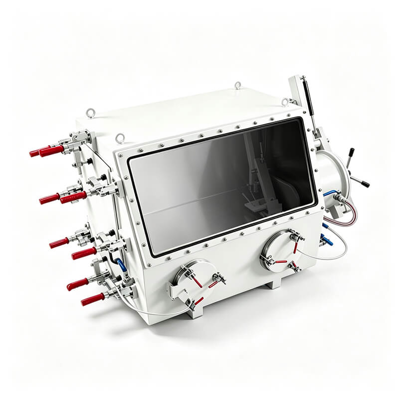
To place the accessory in a realistic setting, consider the class of vacuum glove boxes represented by the GBV-3 stainless steel vacuum glove box. Systems of this type form a controlled environment by sealing a stainless steel chamber, evacuating it, and refilling with an inert gas. That is a different architecture from a box built around a continuously circulating purification system, in which a column removes moisture and oxygen in a closed loop. Neither approach is universally better; they answer different requirements. But they lead to different vacuum trains, and therefore to different accessory questions.
Why the architecture changes the valve duty
On a circulating-purification box, the vacuum train is often limited to the transfer chamber and perhaps a short roughing path, because the main volume is maintained by the loop. On a vacuum-type box, chamber evacuation is part of the routine working cycle, so the pump line sees more use and the valve strokes more often. Cycle life, seat wear, and stroke repeatability therefore carry more weight than they would in an occasional-duty installation. The sequencing question also becomes sharper, because evacuation and backfill must not work against each other, and the state of every valve at each step must be unambiguous. A vacuum-type box should not be assumed to include a continuous purification column, and no valve choice changes that; the atmosphere is managed by the evacuation-and-refill routine and by the quality of the gas supplied.
Compatibility questions to settle before ordering
It is tempting to assume that an accessory from the same supplier bolts directly onto a given box. That assumption is not safe on its own. Confirm the flange or thread standard and nominal size at the box port and at the valve; whether the valve serves the main chamber, an antechamber, or a pump-isolation duty; the seal material relative to the gases and vapours the box will see; the actuator supply pressure and connection type; the control signal and whether position feedback is needed; and the physical clearance around the port for the actuator body and for future service. Only when those items line up does the pairing become a specification rather than a hope. Where details are not published, ask for them in writing instead of extrapolating from a product name or from the fact that two items appear in the same catalogue.
When Behaviour Drifts: Symptoms, Candidate Causes, and Checks
The observations below are possibilities to be verified, not verdicts. A single symptom usually has several plausible causes, and the cheapest path is to separate them by test rather than by replacement.
Pump-down takes longer than it used to
Candidate causes include a disc that is not reaching full open because supply pressure has fallen or a piston seal has worn; a partly blocked line or chamber port; a change in the pump's own performance; a fitting or door seal that has begun to leak; and a chamber releasing more gas than before because surfaces are wet or contaminated. Checks: verify that the actuator reaches its end position, confirm supply pressure at the actuator, compare pump behaviour against a known reference volume, and look at the shape of the rate-of-rise curve, which often distinguishes a real leak from outgassing.
Pressure creeps up after the valve closes
Candidate causes include a damaged or contaminated seat; a seal material that has swelled or hardened; outgassing from chamber surfaces; a leak elsewhere in the system such as a fitting, a feedthrough, or a glove port; and a virtual leak trapped in a blind hole or a threaded joint. Checks: isolate sections using the valves already available, watch the rate of rise rather than the absolute value, and test the seat separately from the rest of the train before condemning the valve.
The valve does not stroke, or strokes erratically
Candidate causes include a pilot solenoid that is not receiving a signal; an air line contaminated with water or oil; supply pressure below the actuator's requirement; a body distorted or misaligned after installation; and a connector that has worked loose. Checks: confirm the signal at the coil, confirm air quality and pressure at the actuator, and inspect the mounting for mechanical stress. Because actuator faults and vacuum faults can produce similar symptoms, testing them separately saves time and avoids replacing parts that were never the problem.
Specification Checklist Before You Order
The checklist below is written for the person assembling a purchase request. It is deliberately short, because the goal is to force the few decisions that actually constraint the selection rather than to reproduce a full datasheet.
| Parameter | Why it matters | What to confirm |
|---|---|---|
| Port size and connection standard | Determines whether the valve can be fitted at all | Nominal bore and flange or thread type at the mating port |
| Open conductance | Sets how much the valve restricts pump-down | Stated conductance compared with the rest of the path and the pump curve |
| Seal material | Governs chemical compatibility and service life | Media the box will see, including solvents and trace oxygen |
| Actuator type and fail position | Defines behaviour when air supply is lost | Spring return or double acting, and the required safe state |
| Air supply | Determines whether a full stroke is reached | Pressure range, air quality, connection size |
| Control signal and feedback | Determines integration with the existing controller | Coil voltage, pilot mounting, position switch |
| Duty cycle | Drives wear and repeatability expectations | Strokes per day and expected service interval |
| Serviceability | Determines downtime when the seat eventually wears | Seal replacement procedure and spare parts availability |
What to send a supplier with the enquiry
A supplier cannot propose a sensible configuration from a product name alone. Useful information includes the chamber or antechamber volume to be evacuated, the pump model and its speed curve, the gases and vapours the line will see, the expected number of cycles per day, the control architecture and available signals, the port dimensions, the clearance around the mounting point, and the sequence the valve must execute. With those items, a proposal can be specific and its limits can be stated openly. Without them, the reply is guesswork dressed as a quotation.
The pneumatic vacuum baffle valve page is the natural starting point for the accessory itself. The engineering work happens around it: deciding which line it gates, what the pump and the chamber demand of it, how it is interlocked, and how its condition will be verified over time. A valve treated as a catalogue line item tends to be discovered again later, during troubleshooting; a valve treated as part of a sequence tends to stay boring, which is the outcome everyone wants.
