
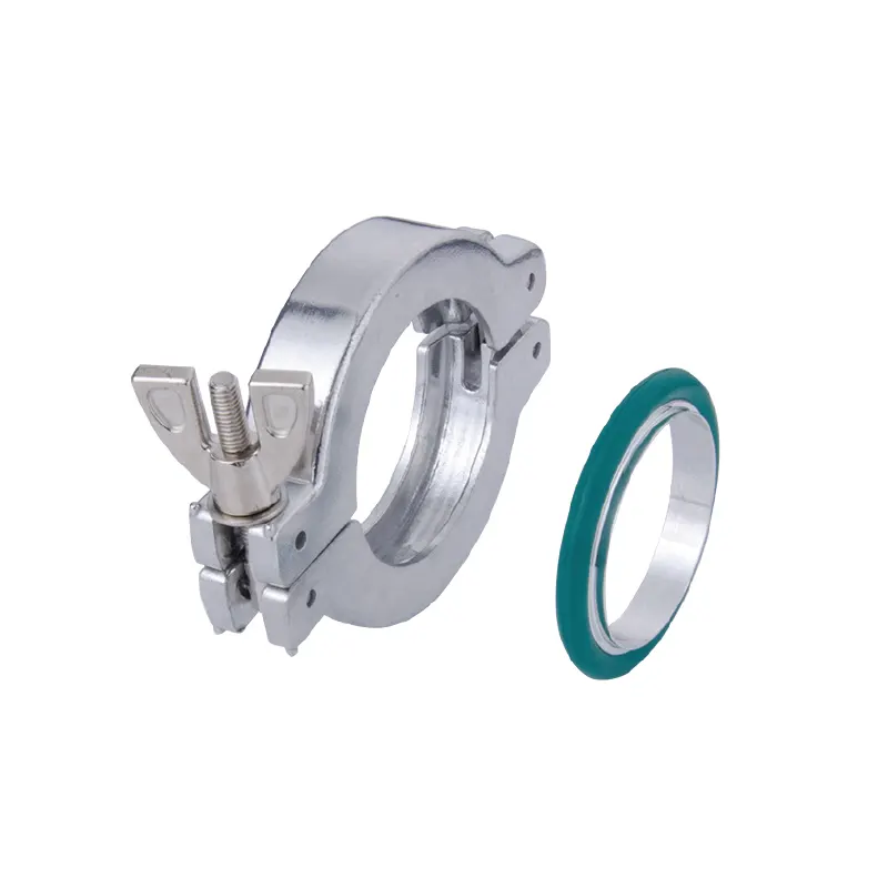
A KF vacuum clamp looks like a minor hardware item: a ring, a lever or a screw, and a few grams of metal. On a glove box, however, that small part sits at the boundary between a controlled atmosphere and the room. It helps hold a vacuum line, a purge connection, or an instrument port together. When the joint is right, nobody notices it. When it is wrong, the symptom may appear far away—slow pump-down, an unstable vacuum reading, a drifting oxygen or water measurement, or an atmosphere that takes longer to recover after a transfer. The TENCAN KF Vacuum Clamp belongs in that system-level conversation, not in a box of generic fasteners.
Why a KF clamp deserves a system-level specification
A KF connection is a demountable joint built around standardized flanges. The clamp is the compression element that holds two flange faces together, but it does not create the seal by itself. The seal is formed by an elastomer O-ring, usually carried in a centering ring that also sets the gap between the flanges. That division of labor matters in a glove box because the joint may be opened repeatedly for pump service, gauge replacement, or line reconfiguration. A clamp that is hard to seat, too short for the flange pair, or poorly matched to the seal can turn a routine connection into a persistent leak path.
What the clamp actually does
The clamp supplies axial force. It must pull evenly, engage both flanges, and remain stable through pressure changes. KF hardware is designed for quick assembly and disassembly; the trade-off is that the seal depends on correct alignment and clean mating surfaces. In a crowded glove box manifold, the clamp may be the only part an operator touches during maintenance. That makes ergonomics part of the specification: a part that cannot be reached properly may be installed inconsistently, even when its dimensions are correct.
What the clamp cannot do
A clamp cannot correct mismatched flange sizes, replace a damaged O-ring, flatten a dented sealing face, or support the weight of a hose. It also cannot improve gas purification, replace a leak test, or convert a chamber that is not designed for vacuum into a vacuum vessel. Those boundaries are obvious in a parts catalogue but easy to forget during troubleshooting. A clamp is an interface component, and its performance depends on the entire sealing stack around it.
Where KF connections appear around a glove box
Depending on the port schedule, KF joints may be found on a pump inlet or exhaust line, an antechamber evacuation line, an inert-gas purge manifold, a pressure gauge connection, a gas analyzer sample line, a solvent trap, a feedthrough housing, or a regeneration exhaust. The exact list belongs to the manufacturer's piping and instrumentation diagram; it should not be inferred from a photograph. The same clamp shape can be used in very different duties, and the duty is what determines the seal material, the required cleanliness, and the maintenance attention.
The Two-Station Double-Sided Glove Box with Gas Purification System shows why port layout matters. A two-station, double-sided enclosure has more access points and more opportunities for a shared line than a small single-station box. A leak at a shared connection may affect both workstations, while a leak on an isolated line may show up only during one transfer step. That does not prove that any particular clamp fits that system. It does explain why the connection schedule should be checked before a clamp is selected.
Rough vacuum and controlled atmosphere are different duties
One clamp might be on a line that is pumped down and refilled, while another sits on a line that is normally under slight inert-gas pressure. The mechanical direction of the load and the gas exposure are different. Vacuum cycling can pull the seal into its groove; positive pressure can push it outward. Neither condition is automatically handled by every clamp and seal combination. The user should confirm the intended service, not just the flange size.
Access, orientation, and tube support
A clamp needs room for the operator's hand or tool. If a hose pulls sideways on the joint, the clamp carries a bending load it was not meant to carry. Support the tube or hose independently, leave enough straight run for the clamp, and make sure the centering ring can be seen and seated before tightening. A joint buried behind other hardware is more likely to be assembled poorly, even when the parts are correct. Good access is not a cosmetic preference; it affects repeatability.
The sealing stack: size, centering ring, elastomer, and surface
The useful question is not simply which clamp to order. It is which sealing stack will be assembled at that port. Four elements matter together: the flange size, the centering ring, the O-ring, and the condition of the mating surfaces.
Nominal size and flange pattern
A KF clamp is matched to a nominal flange size. The size marked on the flange, the centering ring, and the clamp should agree. Do not infer the flange size from the outside diameter of a hose or from the bore of a tube. An adapter adds another joint and another potential leak path. If the two mating flanges are different sizes, a clamp alone cannot bridge them; use the correct adapter or change the flange. When a replacement is ordered, the marking on the existing flange is more useful than a visual estimate.
The O-ring is the actual seal
The O-ring is the actual sealing element. Elastomer choice should follow gas and vapor exposure, temperature, and cleaning. Fluoroelastomer, EPDM, silicone, and PTFE-covered seals have different strengths; none is universal. A seal that swells in a solvent may still look intact while changing the joint clearance. A seal chosen for vacuum may not be the best choice for repeated high-temperature cleaning. The clamp listing should state whether a centering ring and O-ring are included; if they are not, they are separate decisions rather than accessories to assume.
Surface, alignment, and clamping force
Mating faces should be clean, dry, and free of scratches, grit, and dried residue. A fiber or particle on the O-ring can create a leak path that disappears when the joint is disturbed. Tightening beyond the manufacturer's guidance can distort the seal or the flange; under-tightening leaves the joint loose. Use the clamp as intended and check that it engages both flanges evenly. Lubricants should not be applied unless the seal and gas compatibility have been approved, because a lubricant can become a contamination source.
- Confirm the marked flange size on both sides.
- Check that the centering ring is present and correctly seated.
- Verify the O-ring material and condition.
- Clean and inspect the mating faces.
- Support the tube or hose independently.
- Check that the clamp engages both flanges evenly.
Compatibility with purification, vacuum, and sample-transfer hardware
The clamp is interface hardware, not atmosphere-control hardware. A purification system removes water and oxygen through its own columns and circulation loop; the clamp only helps preserve the boundary around that loop. An analyzer measures the atmosphere; it does not purify it, and it does not repair a leaking joint. Keeping these functions separate prevents false claims and makes troubleshooting faster.
Positive-pressure glove boxes
Many glove boxes are kept at a slight positive pressure relative to the room. A KF joint on a purge or sample line may therefore see outward leakage rather than inward leakage. The seal and clamp still need to be correct. The clamp should not be the only restraint for a flexible line, and any quick-disconnect or valve should be supported according to its own instructions. Confirm with the glove box manufacturer whether a particular port is intended for positive pressure, vacuum, or both.
Vacuum antechambers and pressure cycling
An antechamber is a pressure-cycling device. Its pump line may be valved off between transfers, then evacuated again. A clamp on that line should be checked for alignment and seal condition after the system has been opened for service. Repeated cycling can cause a seal to take a set or a fitting to loosen. The point is not that every clamp will fail; it is that pressure cycling is a different duty from a static purge line and should be described accurately when ordering.
Solvent vapors and reactive gases
Solvent vapors are a separate challenge. A solvent trap can reduce the amount of vapor reaching a pump or a seal, but it does not replace water and oxygen purification. A KF clamp does not adsorb solvent, and a clamp with a standard elastomer should not be assumed compatible with every solvent. If the line carries solvent vapor, the seal material and the trap design need to be reviewed together. The same caution applies to reactive gases: inert behavior for one material does not prove inert behavior for every sample or every elastomer.
What the clamp does not add to the system
A clamp does not add continuous purification, regeneration capacity, particle filtration, or oxygen measurement. It also does not make an acrylic enclosure vacuum-rated, and it does not turn a rough vacuum line into a high-vacuum assembly. Those are properties of the chamber, pump, purification loop, and controls. The accessory can only perform its own mechanical and sealing role within limits set by those other components.
When a vacuum reading or atmosphere recovery looks wrong
A slow pump-down, a vacuum that will not hold, or an oxygen and water reading that recovers slowly after a transfer can have several causes. The clamp is one possible contributor, not the default explanation. The useful approach is to separate a leak from outgassing and from a pump or control limitation.
Leak, outgassing, or pump limitation
A real leak admits gas from outside and may be sensitive to pressure, temperature, or valve position. Outgassing releases water or solvent from surfaces and seals; it often decreases slowly with pumping. A pump limitation shows up as a base pressure or pump-down rate that the pump cannot improve, even when the chamber is clean. Before replacing parts, compare the symptom with the system history: what changed, when did it start, and which valve or transfer step makes it worse? A clamp that was recently disturbed deserves attention, but so does a changed gas supply, a new solvent, or a seal that has been exposed to an incompatible vapor.
A practical check sequence
Use a site-approved leak-detection method and the system manufacturer's procedure. A logical check is to confirm valve positions and line identity, inspect the clamp for correct size and engagement, verify the centering ring and O-ring, clean and inspect the mating faces, check tube support and alignment, and then test the joint. Record the flange size, seal material, clamp type, line service, and the result. On a reactive-gas or oxygen-sensitive system, do not introduce a leak-detection fluid unless it has been approved for that service.
What not to conclude from one reading
An oxygen or water reading is not a direct measurement of one joint. Sensor resolution is not the same as accuracy, and readings can lag behind a change in the system. A single high value should lead to a check of calibration, gas flow, and recent transfers before a clamp is condemned. Likewise, a joint that holds vacuum does not prove that its elastomer is compatible with every process vapor. The evidence should match the claim being made.
Specification and procurement checklist for KF vacuum clamps
The available product reference identifies a KF Vacuum Clamp in the glove box accessories category. It does not, in the supplied information, list every size or seal option. That is normal for a compact accessory, and it is a reason to confirm the actual configuration before ordering. A product title alone does not establish compatibility with a specific port, chamber, or gas line.
| Question | Why it matters | What to record |
|---|---|---|
| What is the nominal KF size? | The clamp and both flanges must agree. | Flange marking and a dimension check. |
| Is a centering ring included? | The ring positions the seal and sets the gap. | Included or separate item, with size. |
| Which elastomer is required? | Gas, vapor, and temperature compatibility depend on it. | Process exposure and approved material. |
| Is the line under vacuum, pressure, or cycling? | The mechanical duty affects seal retention. | Line function and valve sequence. |
| How is the hose supported? | The clamp should not carry bending loads. | Support method and available space. |
| What cleaning is required? | Cleaning can change elastomer performance. | Approved agents and procedure. |
Information to give the supplier
A short application note is more useful than a guess based on a photograph. Include the glove box type and the function of the port; the gas or vapor in the line; whether the line is under vacuum, positive pressure, or repeated cycling; the marked flange size on both sides; any known seal-material requirement; the operating and cleaning temperature; access constraints; and the quantity of spares needed for maintenance. If the joint is part of a validated process, include the relevant cleaning and compatibility requirements rather than assuming a standard accessory will satisfy them.
That information lets the supplier check the clamp against the real joint rather than a guessed size. It also makes the order reproducible if the line is rebuilt later. For a small part, the purchasing decision can look trivial. In practice, the clamp is part of a sealed assembly, and the assembly is only as reliable as its least-examined interface.
The KF Vacuum Clamp is a small accessory, but it is doing a system-level job: keeping a demountable joint stable enough for vacuum, purge, or analysis. The right choice depends on the whole sealing stack and the duty of the line. Confirm the flange, the seal, the service, and the access before the clamp goes on the port. That is a more useful specification than a diameter alone.
