
Vacuum glove boxes are often specified by chamber size, glove ports, purifier capacity, and analyzer range. The valve between chamber and pump is easier to overlook, yet it determines whether that vacuum path can be isolated, sequenced, and serviced. TENCAN lists a Pneumatic Vacuum Baffle Valve in its glove box accessories range. The useful questions are what that category does in a vacuum circuit, how to judge whether a particular valve is suitable, and which details must be settled before ordering. It does not assume that every box uses the same port, flange, seal, or control scheme, and it does not treat a valve as a substitute for a pump, purifier, or oxygen analyzer.
A valve is a boundary component. It does not create vacuum, remove water or oxygen, or measure atmosphere; it opens or closes a gas path. That function matters because a vacuum train is a sequence of boundaries: chamber, antechamber, manifold, pump, and vent line. If one boundary cannot close reliably, maintenance, leak checking, and sample transfer become harder. The question is not whether a valve is good in isolation, but whether its connection, seat, actuator, and materials fit the boundary it controls.
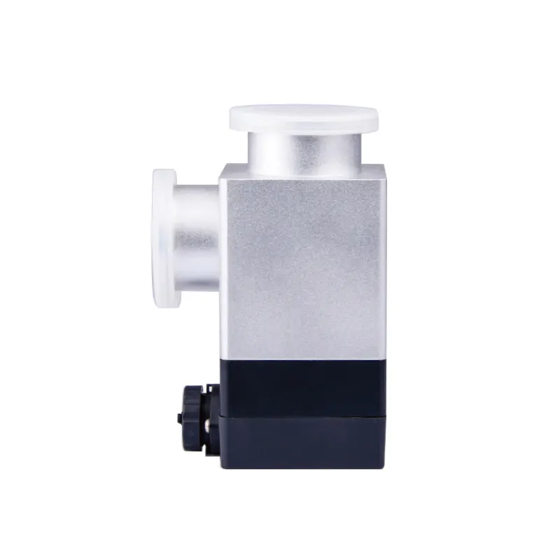
Figure 1. The valve is a controlled boundary in the vacuum train, not a source of vacuum or atmosphere control.
What a pneumatic vacuum baffle valve actually controls
A pneumatic vacuum baffle valve is a vacuum-side valve whose closing element is moved by compressed air rather than by hand. The name describes a construction style rather than a measured performance level. 'Pneumatic' describes the actuator, not the control signal. A solenoid pilot valve, a PLC output, a manual air switch, or a simple air line can command the actuator, depending on the configuration. The product page for the TENCAN Pneumatic Vacuum Baffle Valve is the starting point for the actual connection, dimensions, and actuator details; those details should not be inferred from the category name.
Functionally, the valve has two jobs: provide a controllable gas path and provide a closed position that limits exchange. In a glove box vacuum train, that usually means isolating a chamber from a pump, separating manifold branches, or closing a service connection. Normally closed or open, spring-return or double-acting, with or without position feedback: these are configuration choices, not universal features.
A baffle valve is not a pressure regulator. Unless a product is explicitly designed for modulating service, it should be treated as an isolation valve with a defined open and closed state. Using an isolation valve as a throttle can erode the seat, produce chatter, and make pump-down behavior inconsistent. If the process needs controlled venting or a stable reduced pressure, that function belongs to a device designed for it, not to a valve selected only for shutoff.
The difference between valve types matters during selection. A check valve responds to flow direction and does not normally provide commanded isolation. A manual ball or gate valve may suit a service connection but is less convenient for repeatable sequences. A solenoid valve may be compact and fast, but its orifice and duty cycle may not match a pumping line. A pneumatic baffle valve is often chosen when remote actuation, a short stroke, and a clear open or closed state are useful. None of those preferences replaces a check of vacuum rating, leak rate, and seal materials.
Where the valve belongs in a glove box vacuum train
Valve placement should follow the process flow, not the space available on the frame. In a typical vacuum glove box or vacuum antechamber, the most direct location is between the chamber being evacuated and the pump. The valve allows the chamber to be closed off from the pump for service, leak checks, or a controlled sequence. It also lets the pump run without making the chamber a permanent part of its volume. The actual location depends on whether the system uses a dedicated pump per chamber, a shared manifold, or a combination of bypass and vent lines.
A second location is a manifold branch. When one pump serves more than one chamber, a valve on each branch can isolate the branch not in use. This can reduce cross-talk, but it also adds conductance losses and more seals. A manifold with several valves is not automatically better than a dedicated line; each added boundary is another place to leak, outgas, or be left in the wrong state.
Isolation is not the same as atmosphere control
A valve in the vacuum line does not protect the main glove box atmosphere by itself. The box atmosphere is maintained by the box structure, doors, gloves, purifier, and pressure control. A vacuum valve acts on the vacuum branch. If an antechamber is opened to the box, the box-side door and the transfer procedure control the exchange; the pump-side valve only controls the vacuum path. Closing a valve will not prevent moisture or oxygen ingress unless the whole boundary and transfer sequence are designed for that purpose.
Use the whole machine as context, not as a promise of fit
TENCAN also lists the GBV-3 Stainless Steel Vacuum Glove Box. It is relevant background because a vacuum glove box may include a vacuum antechamber or vacuum process line where an isolation valve is useful. It is not evidence that any particular accessory drops into any particular port. The GBV-3 page and the valve page must be read with the actual port drawing, flange standard, pump connection, and control scheme. A valve that fits one vacuum box may be wrong for another because the flange, seal, or actuator envelope differs.
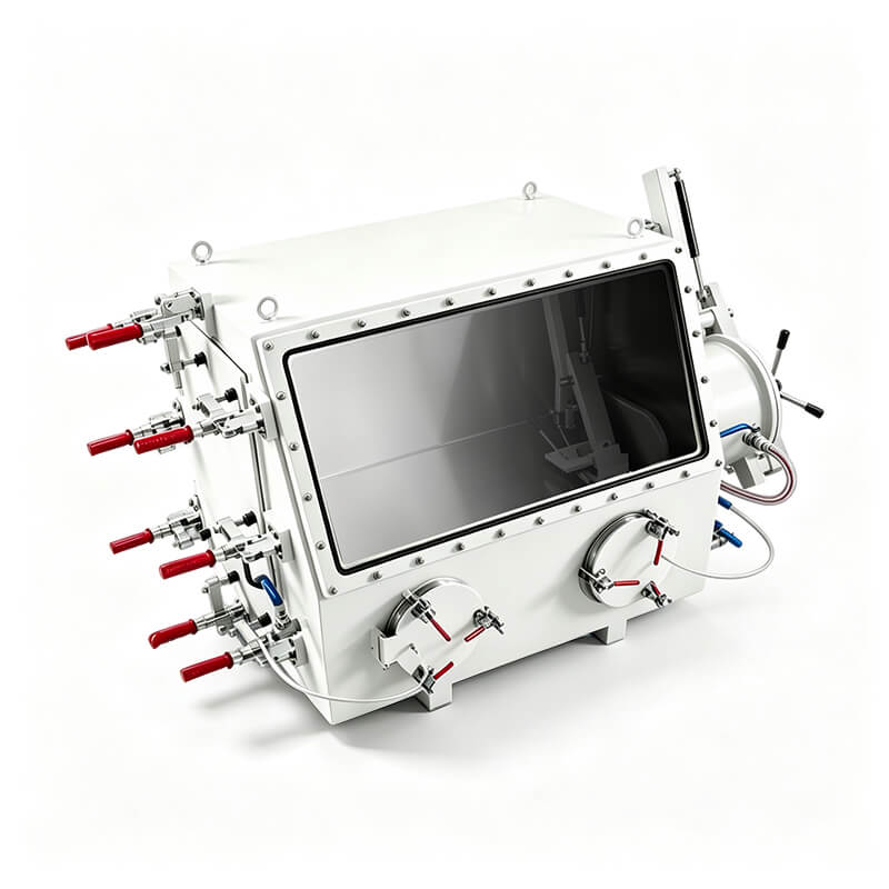
Figure 2. A vacuum glove box provides the host boundary; the accessory must match the actual port and control scheme.
Interfaces are where mismatches occur. Select the accessory after the host boundary is defined, not before.
Pneumatic actuation: benefits, dependencies, and failure behavior
Remote actuation is the main reason to choose a pneumatic valve. The actuator can be operated from a control cabinet, a foot switch, or a PLC, keeping the operator away from the vacuum line. Pneumatic motion can be fast and repeatable, and a piloted valve can be interlocked with a pump, a door, or a vent sequence. Those benefits depend on a clean, stable air supply and a control design that defines what happens when the air supply is lost.
Compressed air is not a detail to settle after mounting. The actuator needs a supply pressure and flow within its specified range, adequate tubing, filtration, and a way to exhaust displaced air. Moisture, oil, or particulates can affect a pilot solenoid or the actuator seals. The exhaust should not blow dust onto the box, create noise in a quiet laboratory, or pressurize an enclosure not designed for it.
Open, closed, and the meaning of fail-safe
Fail-safe is not a universal property. On loss of control air, a spring-return actuator may drive the valve to a defined position, while a double-acting actuator may remain where it was. Which behavior is safer depends on the system. A valve that fails closed may protect the pump from a vented chamber; a valve that fails open may prevent a trapped vacuum from holding a door or chamber in an unexpected state. The correct choice comes from a hazards review of the actual vacuum train, not from the word 'pneumatic'.
Position feedback is a separate question. A limit switch or proximity sensor can tell the control system that the valve has reached an end position, but it does not prove that the seat is leak-tight. A command output is not feedback, and an actuator stroke is not a vacuum measurement. If the process depends on knowing whether the line is isolated, the specification should state the feedback type and the control logic that uses it.
Manual override is useful during commissioning and maintenance, but it should be confirmed rather than assumed. Stroke speed control deserves the same check. A valve that slams open or closed can send a pressure transient through the chamber, disturb a sample, and stress the seat. Speed control or a suitable pilot arrangement may be needed; these are integration choices, not improvised start-up details.
Duty is another actuator point. A valve on an antechamber that cycles many times per day is a different application from a service isolation valve that moves a few times per year. Cycle frequency, seal wear, and spare parts should be discussed with the same seriousness as the vacuum rating. A component can be technically compatible and still be a poor choice for the actual operating rhythm.
Compatibility and sizing checks before ordering
Connection is the first gate. Vacuum systems use several connection families, and each has its own clamp, seal, and tightening method. A photograph of a port is not a substitute for a drawing with dimensions and a standard. The valve must match the mating flange, seal groove, tube size, and available clearance for the actuator. Do not infer a KF, ISO-K, CF, or threaded connection from a product category or a similar-looking image. If the host has a non-standard port, an adapter may be possible, but it adds a joint and must be reviewed as part of the vacuum boundary.
Seal material is the second gate. A leak-tight valve is only leak-tight within its intended material and temperature envelope. Elastomer seals, PTFE seals, and metal seals behave differently under vacuum, solvent exposure, and thermal cycling. The process gas matters as well. Oxygen, corrosive gases, and solvent vapors can change seal life or create a compatibility problem that a generic vacuum rating does not capture. Ask for the seal material, temperature range, and any restrictions on gas or vapor. If the answer is not available, do not fill the gap with an assumption.
Conductance is often more important than port size
A vacuum valve can become the limiting restriction in the pumping path. The pump may have a high pumping speed at its inlet, but the chamber sees the effective speed after the conductance of the valve, tubing, and ports is considered. A valve with a narrow internal passage can dominate pump-down time, especially in the molecular-flow regime. A large external flange does not automatically mean a fast evacuation path. The useful evidence is a conductance curve, an equivalent orifice value, or a clearly stated test method, not a claim that the valve is 'high flow'.
The same logic applies to the closed state. A seat leak rate is different from a body leak rate. The body may be vacuum-tight while the seat passes gas, or the seat may seal well while the actuator feedthrough leaks. Ask how each is specified and at what differential pressure. Also ask whether the leak rate is measured with helium, air, or another method, and whether the value is a guarantee or a typical result. A number without a method and boundary condition is difficult to use in a design review.
A compact compatibility matrix
| Check | Why it matters | What to request |
|---|---|---|
| Port and flange | Mechanical fit and seal geometry | Drawing, standard, dimensions |
| Seal material | Chemical and temperature compatibility | Material grade, range, gas restrictions |
| Vacuum and leak | Operation, outgassing, and isolation quality | Rated range, leak rate, differential pressure, method |
| Conductance | Pump-down speed | Curve or equivalent orifice |
| Actuator | Control and failure behavior | Air pressure and flow, fail position, feedback |
| Mounting | Actuator clearance and mechanical stress | Orientation limits, weight, envelope |
Reading vacuum behavior: what the valve can and cannot tell you
When a vacuum problem appears, the valve is only one possible contributor. A slow pump-down can come from a valve that is not fully open, an actuator that is not reaching its end position, a swollen or contaminated seal, a blocked exhaust, an undersized pilot line, a worn pump, an outgassing chamber, or a leak elsewhere in the train. The correct response is to separate the branches and test them, not to replace the valve first because it is the easiest part to reach.
A valve that chatters or cycles unexpectedly may be responding to unstable pilot pressure, a leaking solenoid, a worn spring, a contaminated bore, or an oscillating control signal. A valve that appears closed but still allows pressure to rise may have seat contamination, a damaged seal, or a differential pressure beyond its design. A valve that is hard to actuate may have a mechanical bind, a lubrication problem where lubrication is permitted, or an air supply below the specified condition. Each symptom points to a different check.
Pressure, water, and oxygen are different measurements
A vacuum gauge measures total pressure. It does not report water concentration or oxygen concentration, and it does not prove that a purifier is working. An oxygen analyzer measures oxygen partial pressure or concentration within its own calibrated range; its resolution is not the same as its accuracy. A moisture analyzer has its own calibration. A valve can isolate a sensor or a chamber, but it cannot make a reading valid. If the concern is moisture ingress, check the door seals, gloves, transfer procedure, and purifier; if the concern is oxygen, check the same boundaries and the analyzer calibration. Closing a vacuum valve is not a repair for a contaminated atmosphere.
Particle filtration is another separate function. A HEPA filter captures particles; it does not remove water vapor or oxygen, and it does not replace a molecular purifier or a vacuum-tight seat. Solvent adsorption is also separate from water and oxygen removal. An accessory can be correctly installed and still fail to solve the problem it was never designed to solve.
If the system has a rate-of-rise test capability, it can compare an isolated section with the rest of the train. The point is not to assign a pass or fail value without a specification; it is to locate the source of gas. Isolating the valve from the chamber, then isolating the pump from the valve, can show whether the rise comes from the chamber, the valve seat, or the pump side. The test should follow the system builder's procedure and should account for outgassing after a recent vent or solvent exposure.
Matching the valve to the workflow
A vacuum glove box used for air-sensitive materials may have a busy transfer schedule. In that workflow, the valve is touched by the sequence many times a day: pump the antechamber, isolate it, backfill, open the inner door, and repeat. The important characteristics are repeatability, cycle life, actuator speed, and a clear indication of state. A valve selected only for its flange may fit the port and still annoy the operator if it is slow, noisy, or difficult to interlock.
A solvent-heavy process shifts the emphasis to seal compatibility and cleaning. A powder-handling process shifts it to closure geometry and the risk of particles on the seat. A process with unattended operation shifts it to failure behavior and feedback. A service-only valve can be simpler because it moves rarely and can be operated manually. These are different requirements, and one accessory specification should not be expected to serve all of them equally well.
Do not put the valve where the purifier loop belongs
A glove box with a gas purification system has a closed circulation loop for atmosphere control. That loop has its own valves, blower, purifier columns, and regeneration sequence. A vacuum isolation valve belongs to the vacuum branch, not inside the purifier loop, unless the system was specifically designed with that valve in that location. The two circuits have different pressure regimes, gas quality requirements, and failure consequences. A valve suitable for rough vacuum on an antechamber is not automatically suitable for a purifier circuit, and the purifier circuit should not be modified by adding a general-purpose accessory.
If the application requires continuous atmosphere control, the purchase decision should start with the box and its purification architecture. The valve is then selected as part of the vacuum or transfer subsystem. This order matters because the valve's material, seal, and actuator choices follow from the surrounding design. Starting with a valve and then looking for a place to install it reverses the logic and increases the chance of a mismatch.
Spare parts belong in the same discussion. Seals, pilot valves, and actuator kits determine whether a valve can be maintained or becomes a permanent leak path; ask what is replaceable and whether the seat can be serviced without cutting the line.
What to send TENCAN when requesting a valve
A useful inquiry gives the supplier enough information to say yes, no, or 'this needs an adapter.' The following list is a practical starting point. It is not a substitute for the site's own engineering review, but it prevents common omissions.
- Host equipment and model, with the GBV-3 link if relevant, plus a dimensioned port drawing or photo.
- Vacuum source: pump type, speed, ultimate pressure, and whether dedicated or shared.
- Chamber or antechamber volume, required pump-down time, and whether the valve is for isolation only.
- Connection standard, flange size, seal type, tube size, and actuator envelope.
- Process gas and vapor exposure, including solvents, oxygen, and corrosive species.
- Required vacuum level, differential pressure across the closed seat, and leak-rate method.
- Control architecture: manual switch, solenoid, PLC, interlock, feedback, and fail position.
- Compressed-air quality, pressure, flow, and exhaust route.
- Cycle frequency, expected service life, and spare-parts strategy.
- Cleaning, baking, or temperature limits, and restrictions on elastomer or lubricant use.
Along with the list, send a simple schematic showing the chamber, valve, pump, vent path, and any bypass. A piping and instrumentation diagram or a hand sketch is more useful than a long description because it shows where the boundary is. If an existing valve is being replaced, include its marking, dimensions, and failure behavior. If the goal is to improve pump-down time, say so explicitly; the answer may be a larger valve, a shorter line, or a different pump, and those are not interchangeable fixes.
Finally, separate must-have requirements from preferences. 'Must isolate the pump from the antechamber' is a requirement. 'Would like a compact actuator' is a preference. A supplier can propose a workable configuration only when the two are not mixed. The same discipline applies to internal review: the operator, the pump maintainer, and the process owner should agree on the failure position before the order is placed.
