
Why a Small Valve Shapes the Atmosphere You Measure
Water and oxygen readings get the attention in a purified glove box, and reasonably so. Those readings, though, are the end of a chain that includes the box shell, the gloves, the antechamber doors, the purification loop, the sample lines feeding the analyzers, and the valves that open and close every one of those paths. A valve that seats poorly, actuates slowly, or is fitted to the wrong port becomes a persistent, low-level disturbance that no amount of purifier capacity fully absorbs.
A pneumatic vacuum baffle valve is one of the quieter accessories on a glove box and one of the more consequential. It is a shut-off element in which a baffle, a plate or disc that lifts off its seat with a short stroke, opens or closes the flow path, driven by compressed air rather than a handwheel. Short-stroke closure plus remote actuation is why this family appears on vacuum lines a person cannot easily reach, and on lines that must open and close as part of an automated evacuation-and-backfill sequence.
The vacuum line is a boundary, not a detail
Every vacuum path into a glove box crosses the same boundary twice: once as plumbing, once as atmosphere. On the plumbing side, the valve has to hold against the pressure difference the pump creates. On the atmosphere side, whatever creeps past the seat ends up in a chamber whose entire purpose is to keep outside gas out. Valve selection for glove box service therefore sits closer to vacuum-system design than to general plumbing. The questions are conductance, seat integrity, seal material, and behavior when control air is lost, not thread size alone.
Scope of this article
The sections below work outward from the accessory: how a pneumatic baffle valve functions, where valves of this type sit in an installation, which parameters decide whether a given valve suits a given line, and where the accessory's responsibility ends. The four-station single-sided split-type glove box with a gas purification system listed on this site is used as reference layout for system context. The valve remains the subject, because an accessory specified against the wrong criteria is a problem no host box can compensate for.
How a Pneumatic Vacuum Baffle Valve Works
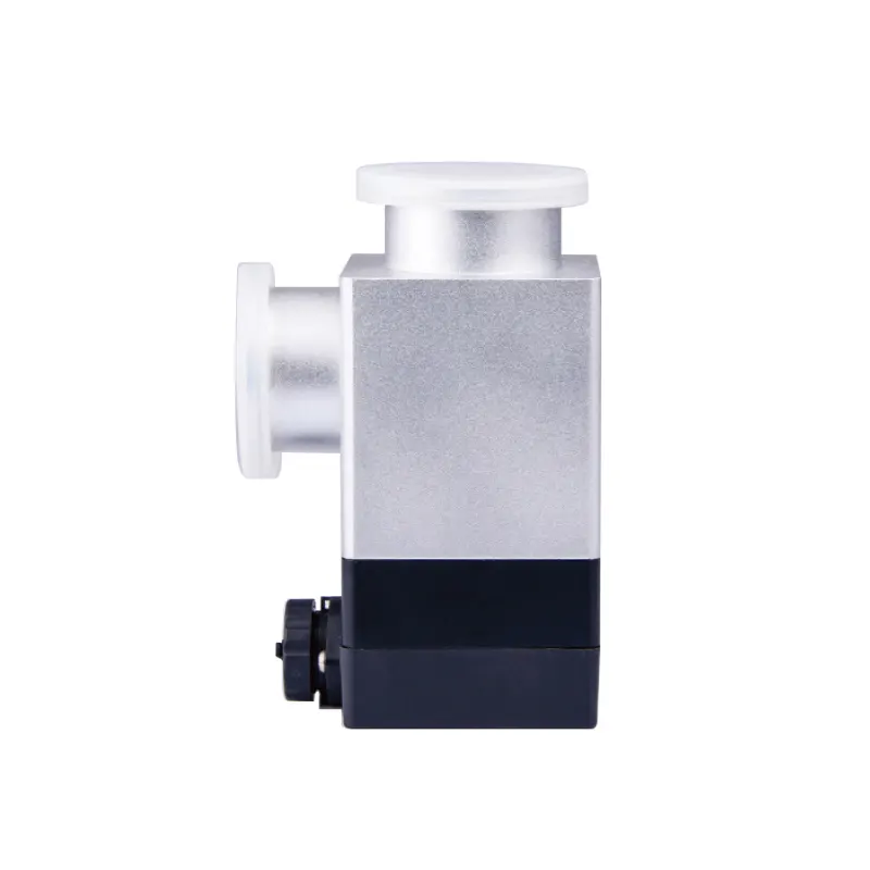
Inside the body, a baffle plate rests against a seat and closes the bore. Pressurizing the actuator moves the plate clear of the seat, and the bore opens. Because the plate travels only a short distance, the valve reaches its open position quickly, and the open flow path stays close to the full bore instead of being throttled by a stem or plug sitting in the middle of the stream.
Baffle geometry and conductance
Conductance is the property that matters most in antechamber work. Pump-down time is set by the pump's effective speed at the chamber and by the conductance of everything between chamber and pump; if the valve is the narrowest element, adding pump capacity buys very little. A baffle closure keeps the open cross-section large for its flange size, which is the practical argument for the design on roughing lines.
The same geometry has a limit. A short stroke gives the closure less mechanical advantage against solid debris on the seat, so the valve benefits from a line that is kept clean and from a seat that can be inspected and replaced. That is a maintenance question rather than a performance claim: the seat and seal in a valve that cycles on every transfer are wear items, and the supplier should be able to describe how they are renewed.
Pneumatic actuation and the control air circuit
Pneumatic actuation exists for two reasons: reach and repeatability. Reach, because the valve is often mounted behind a panel, under a frame, or between components where a handwheel would be awkward or unsafe to operate. Repeatability, because the solenoid pilot valve that switches the control air can be wired into the box's control sequence, so evacuation, hold, and backfill happen in the same order and with the same timing every cycle, independent of who is operating the box.
The control air itself is part of the specification. Suppliers publish a required pressure range, and the valve should be operated inside it rather than at whatever the house air happens to deliver. Air should be dry and oil-free, with a filter-regulator close to the valve: moisture can condense and freeze at the exhaust during rapid cycling in a cool room, and oil aerosols migrate onto elastomer seals. Tubing bore and length affect response time, so a long, narrow run to a small actuator can add noticeable delay. Exhaust flow controls, where fitted, let the user slow closure deliberately, which reduces slamming and seat wear. These values should be compared with the site air supply before installation, not assumed.
Fail position: ask before you mount
The single most useful question about a pneumatically actuated vacuum valve is what it does when control air is lost. Spring-return closed, spring-return open, and double-acting designs that hold their last position are all built, and each produces a different outcome. On an isolation line between an antechamber and a pump, a spring-return-closed valve isolates the chamber when air drops, which is usually the conservative result. A double-acting valve holds its state, which may be preferable where a sequence should not be interrupted by a momentary air dip.
Which behavior a specific pneumatic vacuum baffle valve provides should be confirmed from its current documentation rather than inferred from the design family, because fail position is a configuration decision, not a universal property. The same applies to optional position feedback: a limit switch that tells the control system the valve is fully open before the next step begins is a different product variant from the bare valve.
Where These Valves Sit in a Glove Box System
Antechamber evacuation and inert gas backfill
The antechamber is where the valve earns its place most obviously. A transfer cycle alternates between pulling the chamber down and refilling it with working gas, often several times, before the inner door opens. Each half of that cycle needs a valve that opens fully, closes cleanly, and does so on command. Manual ball valves work, but they depend on the operator's memory and reach; a pneumatically actuated baffle valve lets the cycle be sequenced, timed, and recorded, and removes a hand from a crowded frame.
Valve choice interacts with the antechamber's other design features. A large transfer chamber with a short cycle time rewards high conductance. A small chamber used for delicate parts may be better served by a slower, gentler sequence, because rapid pressure change can move dust or lift light samples. Neither case is a fault in the valve; both are decisions made in the specification.
Isolation between box, pump, and purge paths
Beyond the antechamber, valves separate sections that should not see each other's pressure: the box from the roughing line, one vacuum path from another where a shared pump serves several points, and purge lines from the working loop. Each requirement is slightly different. Box isolation cares about leak integrity at small pressure differentials. Pump isolation cares about conductance and about closing against a running pump. Purge and regeneration lines care about gas and temperature compatibility, and the regeneration sequence itself must come from the equipment manual rather than from an article about valves. Where a valve is proposed for a heated regeneration line, its seal and body materials have to be checked against the actual temperature and gas involved.
What a multi-station layout changes
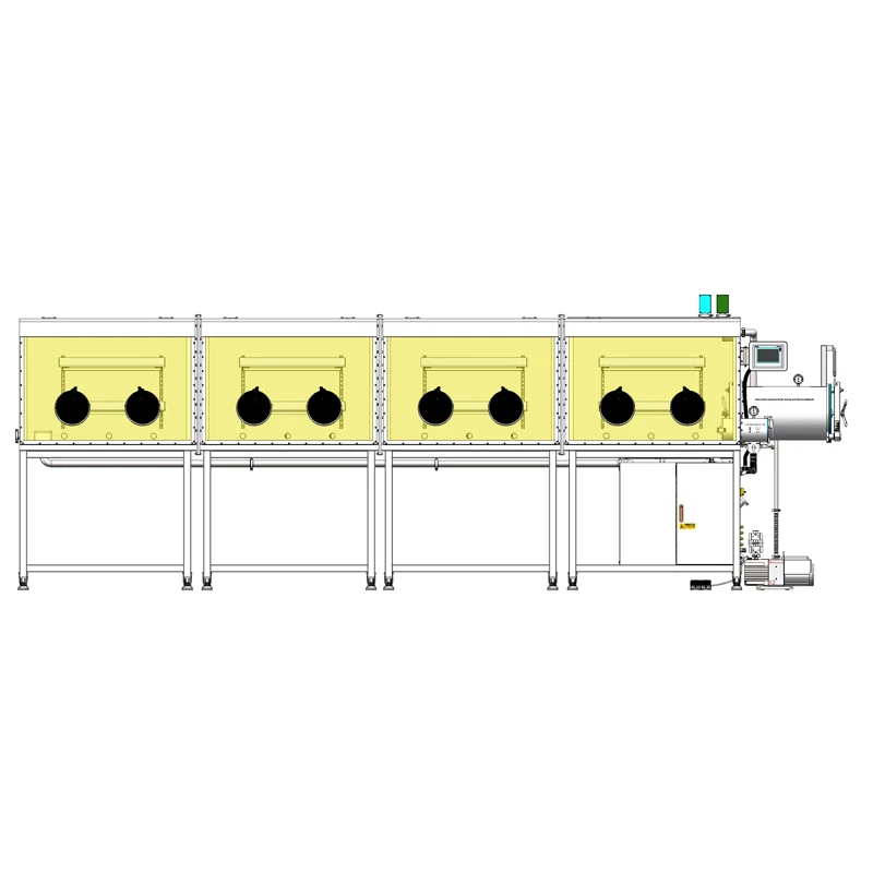
A four-station, single-sided, split-type glove box with a gas purification system, as listed on this site, illustrates the scaling problem. Several work positions share one purification loop, and the split construction separates parts of the enclosure. Layouts of that kind tend to have more vacuum paths, more transfer points, and more reason to isolate one section without disturbing another. The number of valves rises, and so does the value of consistency: identical valves, identical actuators, identical control-air settings, and a documented fail position for each one. Mixed hardware in a shared loop is where troubleshooting becomes expensive.
Selecting the Valve: The Parameters That Matter
Accessory listings rarely carry a complete engineering datasheet, so the practical approach is to define the line first and then ask the supplier to confirm each item in writing. The table below is the short list for a vacuum baffle valve in glove box service.
| Parameter | Why it decides the application | What to request |
|---|---|---|
| Bore and flange standard | Sets conductance and whether the valve mounts to existing hardware without adapters | Confirmed flange type and size, nominal bore, face-to-face length |
| Pressure rating and differential direction | A vacuum valve sees the difference across the seat, not a single absolute number | Rated differential, maximum absolute pressure, and the mounting orientation the rating assumes |
| Leak integrity | Decides whether the valve isolates the line or merely throttles it | Test method, test pressure, acceptance criterion, and which seal sets that criterion |
| Seal and body material | Solvent vapor, amines, and oxygen service all constrain elastomer choice | Elastomer grade, any lubricant used, and whether an oxygen-compatible variant exists |
| Control air specification | Sets response time and actuation reliability | Required pressure range, consumption per cycle, air quality class, port size |
| Fail position | Defines what happens to the atmosphere when air or power is lost | Spring-return or double-acting, and the direction of return |
| Position feedback | Needed if the control system must verify state before the next step | Switch type, contact rating, connector style |
| Cycle life and service kit | A valve that cycles on every transfer is a wear item | Rated cycles, seat and seal replacement procedure, spare parts list |
Leak integrity: how to ask about it
"Vacuum tight" is not a specification. What matters is the test method, the pressure at which it was applied, the direction of the test, and the acceptance criterion. A valve tested with the seat pressure-assisted in one direction may behave differently when mounted the other way around, and a valve that meets a rate specification at a large differential may not hold the same rate at the small differential that matters when isolating a box at working pressure. Ask for the numbers with their conditions attached, and mount the valve in the orientation the rating assumes.
Conductance and pump matching
Selecting a valve and a pump separately usually produces a mismatch. The pump's quoted speed is measured at its inlet; the effective speed at the chamber is reduced by the conductance of tubing, bends, filters, and valves in between. If the valve bore is the smallest restriction in the run, it dominates the result and larger pumps make little difference. Matching the valve bore to the line bore, and keeping the line as short and straight as the frame allows, is more effective than buying speed the plumbing cannot deliver. For a shared pump serving several points, the question also becomes how many paths can be open at once without starving the others, which is a sequencing decision as much as a sizing one.
Control air, feedback, and service access
Three practical items complete the selection. First, control air: confirm the pressure range, the consumption per cycle, and the air quality class, then provide a dedicated filter-regulator and size the tubing for the response time required. Second, feedback: if the sequence must not proceed until the valve is fully open, specify a position switch, because a solenoid command is not proof of movement. Third, service access: the valve will eventually need its seat or seal renewed, and a valve installed with no clearance for removal turns a small maintenance job into a partial teardown of the frame.
Compatibility Boundaries: What the Valve Does Not Do
Accessory language can slide into overreach. A vacuum baffle valve controls flow. It does not condition the atmosphere, and treating it as if it did leads to the wrong purchase.
- It does not remove water or oxygen. That is the purification loop's work, in a system that has one. In a vacuum-type enclosure without continuous purification, the valve supports evacuation and inert gas exchange, which is a different function with different limits.
- It does not filter particles. HEPA filtration is a separate element in the gas path, and a valve upstream of a filter does nothing to protect the chamber from particulate.
- It does not measure. An analyzer reading describes the gas where the sample is drawn, and valve state changes the flow that feeds that sample line.
- It does not replace a solvent adsorber. Solvent vapor management is a separate function with its own media and its own service interval.
- It does not guarantee fit across suppliers. Flange standards look interchangeable until face-to-face length or seal groove detail differs.
The host box is context, not a compatibility claim
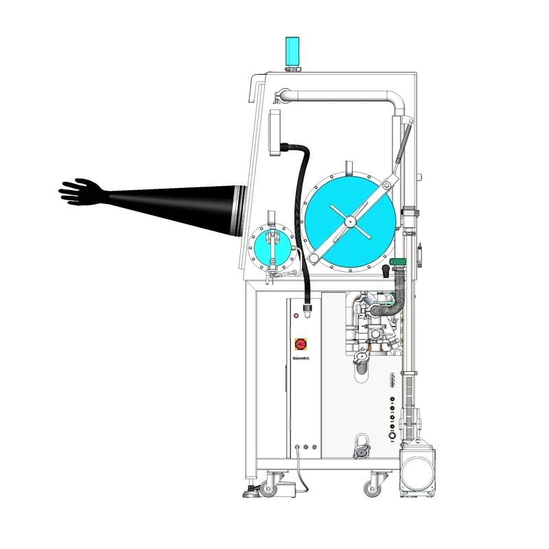
Referring to the four-station single-sided split-type glove box with a gas purification system is useful for one thing: showing the scale at which valve counts grow. It is not evidence that any particular pneumatic vacuum baffle valve is a drop-in replacement for that box's vacuum manifold. Mounting, bore, seal material, and control-air arrangement must be checked against the manifold drawing by whoever holds the system documentation, whether that is the box builder or the accessory supplier. Where the documentation is incomplete, the safe conclusion is that compatibility is unconfirmed, not that it is likely.
Commissioning Checks and Reading the Symptoms Later
Before the first transfer cycle
Commissioning a valve is short if it is done in order. Confirm the mounting orientation matches the pressure rating. Pressure-test the line with the valve closed and then open, and compare the observed leak behavior with what the supplier stated. Cycle the actuator at the minimum control pressure in the specified range, not only at the house pressure, to see whether it still completes its stroke. Verify the fail position by isolating control air deliberately and observing what the line does. If position feedback is fitted, confirm the control system sees the open signal before it starts the next step. Each of these checks takes minutes and prevents the far more common alternative: discovering the behavior during a sensitive transfer.
Slow pump-down after installation
A chamber that evacuates more slowly than expected is not automatically a faulty valve, and it is worth working through causes in order. Start with what changed: a new valve, a new seal, a new pump, or a new sequence. Then check the simplest restrictions, which are usually the valve not reaching full stroke because control air is below the required pressure, a partly closed isolation valve elsewhere in the run, or a clogged filter element. Next, look for a seat obstruction such as particulate or a swollen elastomer, and for condensate or frost in a cold line. Only after those are excluded does it make sense to compare measured conductance against the specification.
Water and oxygen readings that recover slowly
Slow recovery of the analyzer readings after a transfer has several plausible causes, and the valve is only one of them. The chamber may have been open longer than the sequence assumes. The gloves or door seals may be admitting moisture. The sample line to the analyzer may be long, or may be drawing from a point that the purge flow does not sweep well. A valve that is not fully closing on the pump line, or one that leaks past its seat, extends the time the box spends under conditions the purifier has to correct. Distinguishing these requires observation rather than assumption: log valve commands against the analyzer trend, and the answer usually becomes visible.
What to Send a Supplier
Most selection errors are information errors. A supplier who receives a complete description of the line can confirm or reject a valve quickly; one who receives a product name and a hope cannot. The list below is a reasonable packet for a single valve enquiry.
- The gas or gas mixture the line carries, and whether solvent or amine vapor is present.
- Line bore, flange standard, and the space available for the valve body and actuator.
- Maximum absolute pressure and the differential the valve will hold, with the mounting orientation.
- Required leak integrity, stated as method, pressure, and acceptance criterion.
- Cycle frequency and the number of cycles expected between services.
- Available control air pressure, quality, and the response time the sequence needs.
- Required fail position and, if applicable, position feedback and its interface.
- Whether the valve will be used near a heated regeneration line, and at what temperature.
A vacuum baffle valve is a small line item that decides how quickly a chamber cycles, how cleanly a path isolates, and how much atmosphere a box has to recover after every transfer. Specifying it as an engineering component, with its conductance, its seal, its fail position, and its service access defined, is what separates an accessory that quietly does its job from one that is discovered later through a drifting analyzer trace.
