
A glove box filled with argon is not the same as a glove box with a controlled argon atmosphere. Filling is a single act; control is a continuous process that runs every hour the box is in use. Between the two sit practical decisions: how air is removed when the enclosure is first closed, what keeps moisture and oxygen from creeping back during daily work, how samples and tools move in and out, and how anyone knows whether the loop is actually holding. For laboratories working with air-sensitive materials over months rather than hours, the central question is rarely which enclosure to buy — it is whether the atmosphere should be maintained by a dedicated purification system instead of by repeated gas replacement.
This article examines that question through the role of the GP20 Gas Purification System Cabinet, an independent purification unit intended to work with a compatible sealed enclosure or process equipment, and through the smaller components that decide whether the sequence around it performs as intended.
What an Independent Purification Cabinet Does — and What It Does Not Do
The GP20 is a gas purification cabinet, not an enclosure. That single distinction explains most of the confusion buyers encounter. The cabinet has no working space: samples are not placed inside it and no gloves reach into it. Atmosphere is drawn from a sealed enclosure or a piece of process equipment, passed through purification media, and returned to the same volume. The enclosure provides the workspace and the operator access; the cabinet conditions the gas that fills it.
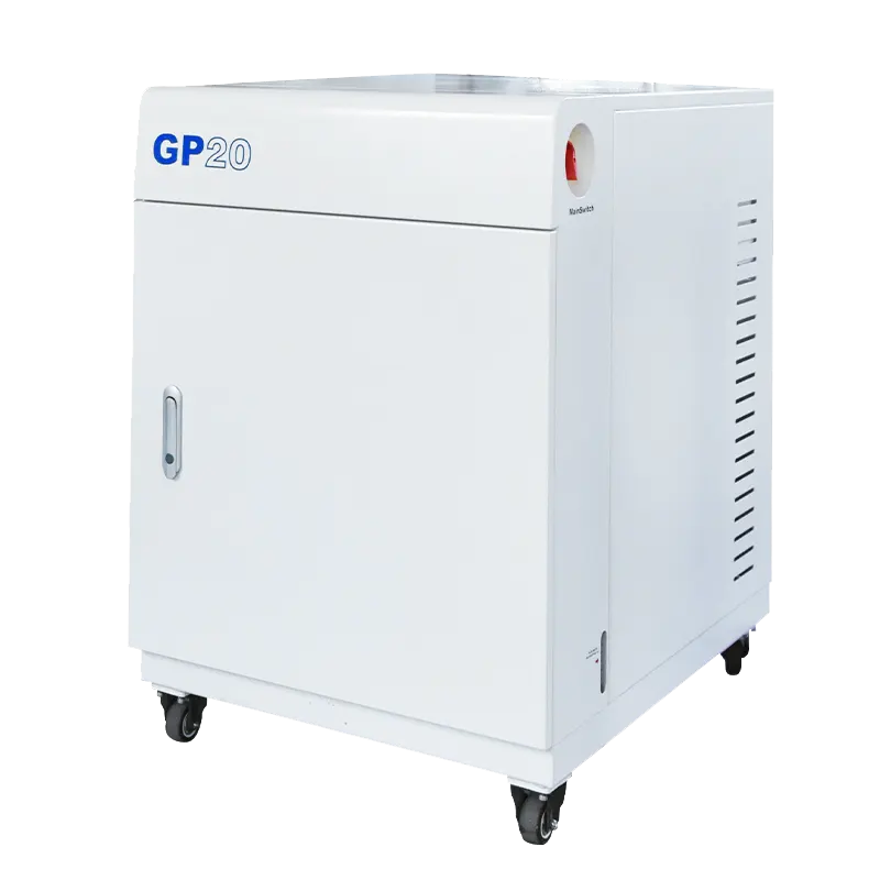
The word "compatible" in that description carries real weight. A purification cabinet is not a universal add-on that can be attached to any box. A closed loop only exists if the enclosure is genuinely closed — leak-tight at gloves, ports and viewports, and stable under the small working pressure the loop imposes. The two units must be joined with appropriate gas lines and fittings, sized sensibly against the total volume and circulation path, and built from materials that tolerate both the working gas and whatever solvent or process vapor the work introduces. Control signals, valve actuation, interlocks and monitoring logic have to be coordinated as well. Any one of these can decide whether a particular pairing is appropriate, and it is a configuration question rather than a brand question.
Three gas streams that should never be confused
A purification system handles at least three distinct gas roles. The working gas is the atmosphere inside the enclosure — the gas that circulates, is purified and is monitored. The control gas drives valves and other pneumatically actuated components and never enters the working volume. The regeneration gas restores purification media that have taken up moisture and oxygen, and it is normally handled with the enclosure isolated from the loop.
These streams have different purity requirements, supply pressures and connection points, and cross-connecting them is a classic commissioning error. The exact requirements for each belong to the specific model's documentation. Ask for them rather than inheriting values from another system or from a rule of thumb.
Purification is not filtration, adsorption, or measurement
Several components sit close together in a glove box installation, and their functions are frequently merged in conversation. A HEPA filter traps particles. It does nothing about water vapor, and it does not remove solvent vapor at the concentrations that matter for atmosphere quality. Solvent adsorption media protect the purification material from organic vapor; they do not replace moisture and oxygen removal, and they can become exhausted on an entirely different schedule. An analyzer measures the atmosphere; it does not clean it. Adding instrumentation does not improve gas quality — it only tells you what the gas quality is, which is a different and often more useful thing.
Regeneration is planned maintenance, not a fault
Purification media have finite capacity. Once they have taken up enough moisture and oxygen they must be regenerated before they can continue to hold the atmosphere at the level the work requires. This is a scheduled procedure rather than a breakdown, and it is normally carried out with the enclosure protected or isolated. The sequence, the gas, the permissible temperatures and the duration are model-specific and should come from the manufacturer's documentation, not from general principles or from a different machine's practice.
Purge, Evacuation, Circulation, and Regeneration: Four Different Jobs
Most misunderstandings about glove box atmospheres come from treating four operations as interchangeable. They are not. Each solves a different problem and carries its own limit.
Gas replacement (purging): removal by dilution
Purging introduces inert gas into the enclosure and lets the mixture leave, so the concentration of air falls as the volume is exchanged. It is simple, requires no special enclosure design, and works in any sealed box with a suitable inlet and outlet. Its efficiency is limited by mixing and dead volumes: corners, glove wells, pipework and the space behind panels hold air that exchanges slowly, and each additional volume exchange costs gas. Purging is an effective way to bring an enclosure from air to a workable starting condition, but the residual background it can hold is a compromise.
Evacuation and refill: removal by pressure cycling
Pumping a volume down and refilling it with inert gas removes air more completely than dilution, because the air is physically extracted rather than mixed away. It also removes much of the moisture adsorbed on internal surfaces — until those surfaces equilibrate again, a process that continues after the refill is complete. The limits here are structural rather than electrical. An enclosure must be designed to withstand the pressure difference, and large unsupported surfaces, viewports and gloves behave differently under vacuum. Whether a given box can be evacuated, and to what level, is a question for its own specifications, not something that can be carried over from one enclosure type to another.
Circulation through purification media: removal of continuous ingress
Once a box is closed and stable, air still arrives. It comes through small leaks, through permeation of polymer materials, through glove walls, through every transfer, and out of the samples themselves. That is the load a purification loop is built to handle: a slow, continuous, low-level influx. Circulation passes enclosure atmosphere through purification media and returns it, removing incoming moisture and oxygen as they appear. It is steady rather than fast. Raising the circulation flow does not raise the capacity of saturated media, and a purification loop cannot be expected to recover from a large air ingress as quickly as a purged or evacuated transfer removes it.
Regeneration: restoring capacity
Regeneration restores purification media, and while it runs, the purifier is out of service. Either the enclosure is isolated at the same time or the work pauses. Planning regeneration around experiments is part of operating a loop properly; on busy installations, scheduling it into quiet periods is often the difference between a system that supports a project and one that interrupts it.
| Operation | Primary purpose | What limits it | What to confirm |
|---|---|---|---|
| Purge | Bulk replacement of air with inert gas | Mixing, dead volumes, gas consumption | Number of exchanges required; acceptable residual level |
| Evacuate and refill | Physical removal of air and surface moisture | Enclosure and glove mechanical limits; pump compatibility | Whether the enclosure is rated for vacuum; gas-to-pump compatibility |
| Circulate | Continuous removal of ingress during operation | Purification capacity, flow path, leak rate | Leak-tightness; circulation path; sensor location |
| Regenerate | Restoring purification capacity | Isolation requirement; gas supply; schedule | Documented procedure for the specific model |
When a Closed Loop Is the Right Answer — and When It Is Not
The deciding condition is usually duration and stability rather than peak sensitivity. A closed purification loop makes sense when an enclosure has to hold a low, steady background for weeks or months, when access is frequent, and when the alternative — repeated purging — would consume large volumes of gas without ever reaching the level the work needs. It is the standard arrangement for long-running experiments where the atmosphere is part of the experiment rather than a preparation step.
The same logic points away from a loop in other cases. If an enclosure is used occasionally, if it cannot be made leak-tight, if the work introduces materials incompatible with the loop's wetted parts, or if the enclosure volume is too large for the circulation path available, a purge-and-refill routine may be the more honest choice. Buying a purification cabinet does not fix a leaking box; it simply adds capacity that the leak consumes.
Geometry and access matter as much as volume
Two enclosures with the same internal volume can behave very differently in a loop. Interior surface area, the number of gloves, the number of transfer ports, the number of sealed joints and the amount of polymer exposed to the atmosphere all influence how quickly the box recovers after a disturbance. A single-station box with light traffic is a different proposition from a multi-station, double-sided enclosure that several people use at once. More access points mean more opportunities for ingress and more volume to circulate; fewer access points mean longer transfers and more awkward work. That trade-off is operational, and it should be settled before purification capacity is specified, not after.
Specify the loop, not two separate machines
A purification cabinet and the enclosure it serves are one system. When they are purchased separately, interfaces that nobody owns tend to appear: the gas connections, the control integration, the sensor placement, the alarm handling, and the question of who verifies leak-tightness before the loop is started. Assigning those responsibilities early — ideally to one supplier or to one clearly defined commissioning plan — avoids most of the disputes that arise weeks into operation.
Reading the Numbers: Pressure, Vacuum, Leak Rate, Oxygen, Moisture
Specification sheets mix several quantities that look similar and mean different things. Keeping them apart is the fastest way to compare systems honestly.
Different quantities, different objects
Enclosure working pressure describes the small positive or negative pressure held inside the box during operation, often quoted in pascals, millibars or inches of water column. Transfer chamber vacuum describes how far the ante-chamber is pumped before it is refilled, quoted in millibars or pascals. Pump ultimate vacuum is a property of the pump at its inlet, without load, and it says nothing directly about the atmosphere inside a box. Leak rate describes how quickly a sealed volume loses or gains pressure, in units such as mbar·L/s or as a pressure decay over time. Oxygen and moisture readings describe the atmosphere at a particular measurement point, at a particular moment, with a particular sensor.
None of these can substitute for another. A pump specified for a very low ultimate vacuum does not guarantee a dry enclosure; a low leak rate does not guarantee a low oxygen reading if purification is offline or the media are exhausted.
Resolution is not accuracy, and accuracy is not stability
An analyzer may resolve very small changes while carrying a much wider accuracy tolerance, and its reading may drift between calibrations. What matters for atmosphere control is whether the reading is trustworthy over the period of the experiment, which depends on sensor technology, calibration practice, cross-sensitivity to other species present, and where in the loop the sensor sits. A sensor placed in a quiet corner of a large box reports the atmosphere in that corner. Circulation pattern, not sensor quality, often decides whether that reading represents the working area.
Values that should be confirmed rather than assumed
When a published figure does not state its reference point, its unit or the configuration it was measured in, treat it as unconfirmed. Ask which quantity is being quoted, how it was measured, under what conditions, and whether it represents a design limit or a demonstrated result. That difference is exactly the difference between a system that meets a specification on paper and one that holds the atmosphere your samples need.
Pneumatic Vacuum Baffle Valve: A Small Component with a Sequence-Critical Role
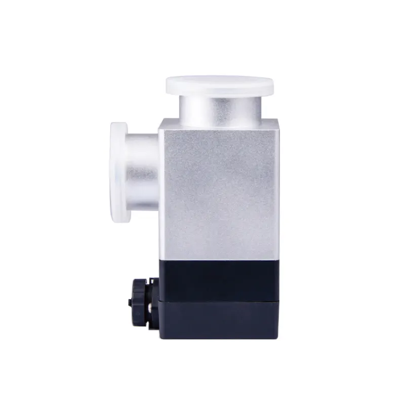
Purification capacity gets the attention, but the sequence around it decides how well the loop performs. Among the components that shape that sequence is the pneumatic vacuum baffle valve.
A baffle valve is a vacuum isolation valve in which a plate or disc closes against a seat to block a line. In the pneumatic version, the stroke is driven by compressed air rather than by hand, which allows the valve to be operated remotely and tied into a control sequence. That matters in a glove box installation for a practical reason: once the enclosure is sealed and the atmosphere is under control, nobody wants to reach into the loop to work a manual valve, and no one wants a pump-down step to depend on someone remembering to turn a handle.
Typical duties include isolating a vacuum pump from a chamber, sequencing pump-down and venting so that a chamber is never opened to the pump abruptly, sectioning a vacuum line so that part of the system can be serviced without breaking the rest, and protecting a pump from a sudden rush of gas or particles. In a system built around transfers, the same valve may sit in the evacuation path of a transfer chamber, opening and closing in step with the purge and refill sequence.
What to confirm before specifying one
- Flange and interface standard. The valve has to mate with the existing line, whether that is a KF-style connection or another standard. The wrong interface turns a simple accessory into a machining job.
- Seal and lubricant materials. Anything wetted by the working gas sits inside the loop's cleanliness boundary. Elastomer choice, grease presence and outgassing behavior matter when the target is low and the valve cycles frequently.
- Actuation supply. Pneumatic valves need clean, dry compressed air at a defined pressure, available at the valve location and stable over time.
- Duty and leak-tightness class. A valve that isolates a line during pump-down has different requirements from one that merely trims flow, and cycle life should match how often the sequence runs.
- Control and feedback. If the valve is driven by the purification cabinet's sequence, confirm signal type, available voltage or pressure, and whether position feedback is required.
- Conductance versus port size. An undersized valve can throttle a pump-down, and an oversized one is unnecessary if the line itself is the restriction.
What a valve does not do
A valve controls flow. It does not purify gas, and adding one does not change the capacity of the purification loop or the leak rate of the enclosure. Nor should a specific valve be assumed compatible with a specific cabinet without confirming the interface and the sequence logic: accessory compatibility is answered by matching specifications, not by assuming that products from one catalog automatically work together.
Transfers, Recovery, and Why a Reading Sometimes Recovers Slowly
Every transfer disturbs the atmosphere. A sample, a tool or a container entering the box carries a boundary layer of laboratory air on its surface, and the transfer chamber itself holds a volume of air that has to be removed before the inner door opens. Two variables dominate the disturbance: the volume of the transfer chamber relative to the enclosure, and the number of purge or evacuation cycles performed before opening.
Why recovery can look slow
When the reading climbs after a transfer and settles back slowly, several mechanisms may be involved, and the right response depends on which one dominates.
- Sensor behavior. Sensors have response times, so readings lag real changes. A sensor downstream of a purifier can also report a cleaner value than the working zone sees.
- Surface exchange. Moisture adsorbs on interior surfaces and desorbs slowly. A box recently opened to air keeps releasing water for a long period, so the apparent recovery curve reflects surface equilibrium rather than the purification media alone.
- Continuous ingress. Small leaks, permeation through polymer materials and glove walls admit a steady trickle. A loop that never quite reaches its target may be fighting an ingress rate it was not sized for.
- Purifier condition. Media approaching the end of their working cycle remove less per pass, so recovery slows before it stops.
- Flow path and circulation. Dead zones, blocked paths or a poorly placed return line leave part of the enclosure poorly swept, even when the loop runs correctly.
- The load itself. Solvent-bearing samples, high-surface-area powders and materials that outgas keep feeding the atmosphere for as long as they are inside.
Diagnosing without jumping to conclusions
A slow recovery is a symptom, not a diagnosis. Useful evidence includes a pressure-hold or leak test of the enclosure, a comparison of readings at more than one point in the box, a log of recovery curves after known disturbances, and a record of transfer frequency and regeneration dates. If recovery consistently stalls at the same level, ingress or media condition is a more likely explanation than an instrument fault. If the reading is noisy or disagrees with a second measurement point, the instrument and its location deserve attention first. In either case, the useful next step is data, not a parts order.
What to Provide Before a System Is Specified
Purification cabinets are configured rather than simply selected, and the quality of the configuration depends on the quality of the application information supplied. A supplier needs the following before proposing a loop that will hold the atmosphere the work requires.
- Enclosure details: internal volume, single or multi-station, single or double-sided, materials of construction, number of gloves, viewport arrangement, and whether the enclosure is designed to accept vacuum.
- Working gas and target conditions: the gas to be used, the moisture and oxygen levels required, and whether those levels apply to the working zone or to a specific measurement point.
- Duty cycle: hours of operation per day, transfers per shift, and expected number of door or port openings.
- Materials handled: sample types, solvents, powders, and anything that could attack seals, gloves or purification media.
- Transfer arrangements: transfer chamber volume, purge or evacuation cycles used, and whether transfer hardware is already installed.
- Utilities: compressed air quality and pressure for pneumatic components, electrical supply, exhaust provisions, and available floor space around both the enclosure and the cabinet.
- Monitoring and regeneration logistics: which species must be measured and where, whether readings must be logged or alarmed, the regeneration gas supply, and how work will be scheduled around regeneration.
Two questions are worth asking explicitly at the end of any specification discussion. First, what exactly is the loop expected to hold, measured where, and under what access conditions? Second, which component in the proposed configuration is the limiting one? A configuration that answers both can be commissioned, verified and maintained — and a purification cabinet, connected to an enclosure that suits it, is only as good as the answers to those two questions.
