
In a glove box, atmosphere control is usually discussed in terms of purifier columns, oxygen and moisture analyzers, and the quality of the inert gas supply. Those are essential, but they are not the whole system. Every time a sample passes through an antechamber, every time a vacuum line is pumped down, and every time a pump is isolated for service, the box depends on vacuum components that are easy to overlook. The Pneumatic Vacuum Baffle Valve is one of those components. It does not create a controlled atmosphere and it does not remove oxygen or water. Its job is to make the vacuum side of the system controllable, repeatable, and safer to maintain.
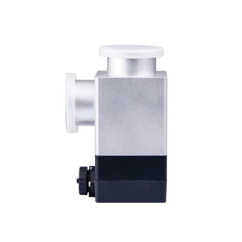
That distinction matters when specifying a glove box. A valve can look like a minor accessory, yet an undersized or poorly selected valve can make an antechamber evacuate slowly, prevent a pump from being isolated cleanly, or introduce an unnecessary maintenance point. Conversely, a well-matched valve supports a logical evacuation sequence and gives operators a clear boundary between the chamber, the vacuum manifold, and the pump.
What a Pneumatic Vacuum Baffle Valve Does in a Glove Box
A pneumatic vacuum baffle valve is a vacuum-line valve whose closure is moved by compressed air rather than by hand. The word “baffle” refers to a closure element positioned in the flow path; the exact internal geometry, seat design, and stroke are product-specific. In a glove box installation, the valve is normally part of the vacuum circuit rather than the inert-gas circulation loop. It opens to allow evacuation and closes to isolate a volume from the pump or manifold.
That basic function supports several practical tasks. The valve can isolate an antechamber after transfer, separate a pump from a line during maintenance, divide a vacuum manifold into sections, or provide a controlled boundary while another part of the system is being serviced. In automated systems, the pneumatic actuator allows the valve to be operated by a solenoid or a central control sequence rather than by reaching into the work area.
Isolation, conductance, and control are not the same thing
It is useful to separate three jobs that are sometimes lumped together under “valve.” Isolation means stopping flow and separating two volumes. Conductance describes how easily gas travels through the open valve; a narrow or convoluted path can limit pumping speed even when the valve is fully open. Control means deliberately modulating flow or pressure, and that requires a valve designed for modulation. A general-purpose baffle valve should not be assumed to be a precision leak valve, a proportional pressure controller, or a metering valve unless the product documentation explicitly says so.
Likewise, the valve is not a purifier, a solvent adsorber, or an oxygen analyzer. A purifier removes water and oxygen from the circulating gas. A solvent adsorber targets organic vapors. An analyzer measures the atmosphere. A vacuum valve only manages the path through which gas is removed. Treating these functions as interchangeable leads to poor specifications and disappointing performance.
A useful way to think about the valve is as a movable boundary. When it is open, the chamber and pump share a pressure history. When it is closed, they do not. The quality of that boundary depends on the seat, the actuator force, the flange seals, and the installation. A valve that leaks slightly may still be acceptable for rough vacuum but unacceptable when the line must hold a stable pressure during a transfer. That is why the required leak rate should be tied to the task rather than chosen from a generic catalog description.
Where the Valve Fits in a Glove Box Vacuum Architecture
The exact location of a pneumatic vacuum baffle valve depends on the box layout, but the usual logic is a series path: the volume to be evacuated, the valve, the vacuum line, and the pump. The valve may sit close to an antechamber, on a manifold, or at the pump inlet. Each position has consequences. A valve close to the chamber can isolate a short section of line, but it may be exposed to more particulate or condensable material. A valve at the pump inlet protects the pump but leaves a longer line under vacuum. The right choice depends on what must be isolated and what must be cleaned or serviced.
Line size and route deserve as much attention as the valve itself. A valve with a restrictive bore can dominate the conductance of the whole circuit. Long flexible hoses, sharp bends, and unnecessary reducers have a similar effect. If an antechamber takes longer to pump down than expected, the cause may be the pump, a leak, a seal, the gauge location, or the conductance of the line—not necessarily the valve. The point is to treat the vacuum path as a system rather than as a collection of unrelated fittings.
Manifold design is part of the same problem. If several chambers share one pump through a single manifold, one open valve can change the pressure seen by another branch. A valve that isolates one chamber may not isolate the manifold from the pump unless the layout provides that separation. Designers should draw the vacuum schematic and mark which valves isolate which volumes, rather than assuming that every closed valve creates the same boundary.
Transfer chambers and atmosphere disturbance
The transfer chamber, or antechamber, is where operators most often notice valve behavior. A typical sequence involves isolating the chamber from the glove box atmosphere, evacuating it, refilling it with inert gas, and then opening it to the box. The valve supports the evacuation part of that sequence. It does not by itself prevent atmosphere disturbance during transfer; the door seals, the chamber volume, the number of purge cycles, and the operating procedure all matter.
When specifying a valve for this duty, ask what is being pumped: air during initial pump-down, inert gas during routine transfer, or process vapors from a sample. Ask how often the chamber cycles and whether the line can collect particles. A valve that is suitable for clean inert gas may not be suitable for a line carrying solvent vapor or powder. Those are compatibility questions, not just vacuum questions.
Multi-station layouts and shared vacuum services
Multi-station and split-type glove boxes add another layer. A six-station double-sided split-type system, such as the Six-Station Double-Sided Split-Type Glove Box with Gas Purification System, illustrates how several work zones can share a purification system while presenting multiple transfer points and vacuum demands. The valve selection for such a project is not simply a matter of copying a single-station bill of materials. The designer has to decide which volumes are isolated together, which pump serves which line, and whether simultaneous use by several operators is acceptable.
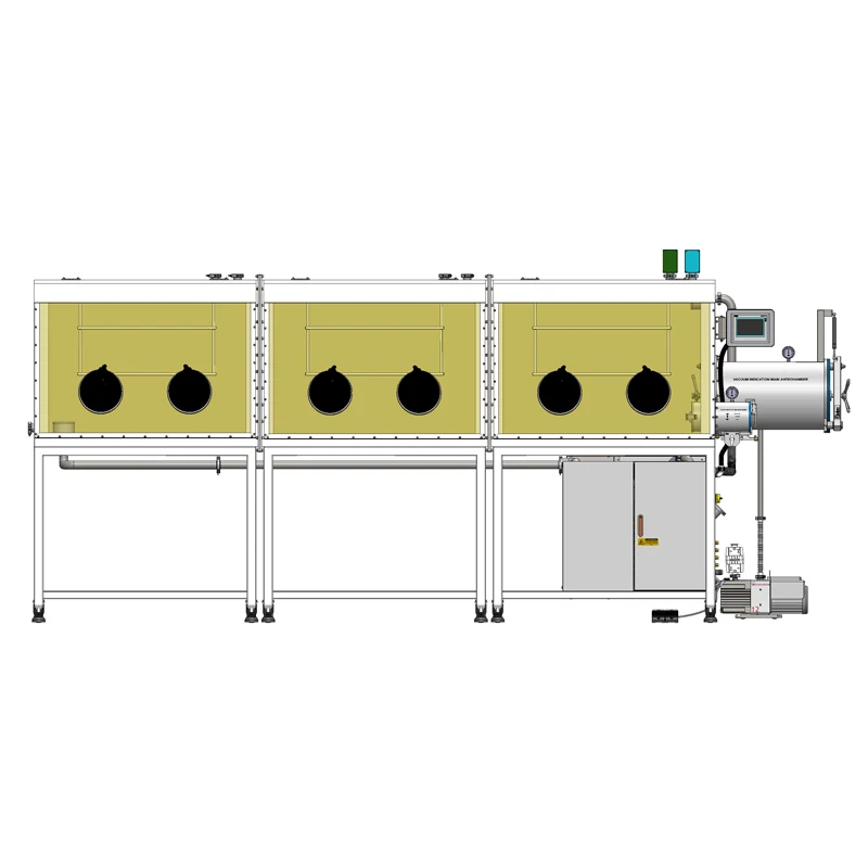
This is also where compatibility claims should be handled carefully. The existence of a multi-station box and a pneumatic vacuum baffle valve in the same product portfolio does not prove that every valve variant is correct for every port on that box. Flange size, seal material, actuation logic, and control sequence still have to be checked against the actual configuration.
Pneumatic Actuation: Air, Spring, and Fail-Safe Position
The pneumatic actuator is the feature that distinguishes this valve from a manual ball valve or a simple hand-operated isolation valve. Compressed air drives a piston or diaphragm, which moves the closure. A solenoid valve, often mounted nearby or in a control panel, directs the air. The actuator may be spring-return or double-acting, and the valve may be configured to fail closed or fail open when air is lost. Those choices affect how the vacuum system behaves during a power interruption, an air-supply failure, or an emergency stop.
“Normally closed” and “normally open” can be confusing because the words describe the actuator’s rest state, not necessarily the safest state for the process. A normally closed valve may be desirable when the priority is to isolate a chamber from the pump. A normally open valve may be desirable when the priority is to keep a pump line open and avoid trapping pressure. The correct choice comes from a hazard review of the specific system. It should not be inferred from the product name alone.
Control details also matter. Does the valve need a position feedback switch so the control system knows whether it is open or closed? Is a manual override required for maintenance? How often will it cycle? Is the compressed air dry and filtered? Is the solenoid voltage compatible with the panel? These questions are mundane, but they determine whether a pneumatic valve actually delivers the remote operation that motivated its selection. A valve that needs an air line, a solenoid, and a feedback cable is not automatically more reliable than a manual valve; it is a different trade-off between automation and simplicity.
The choice between pneumatic and manual operation is therefore an architecture decision. Pneumatic actuation is useful when the valve must be operated from a control sequence, when it is located in a position that is awkward to reach, or when several valves must move in a defined order. Manual operation is simpler and removes the dependence on compressed air, but it requires access and introduces human variation. Neither choice is universally superior. The right answer depends on the required repeatability, the available utilities, and the maintenance philosophy of the laboratory.
Vacuum, Seal, and Material Compatibility
The word “vacuum” covers a wide range of conditions. A valve used on a rough-vacuum transfer line is not necessarily suitable for a high-vacuum manifold, and a valve that holds pressure in one direction may not be intended for reverse flow. No single pressure rating or leak rate can be applied to every installation; those values must be confirmed for the specific variant and application.
Four compatibility questions are especially important. First, what is the flange or connection standard, and does it match the chamber, line, and pump? Second, what are the wetted materials and seat seals, and are they compatible with the process atmosphere, cleaning agents, and any solvent vapors? Third, what pressure range and leak rate are required, and are those values stated for the same direction and test method? Fourth, what conductance is needed at the expected flow, and is the valve bore adequate? A valve can be vacuum-tight and still be a poor choice if it throttles the pump.
Leak rate and pressure decay are related but not identical. A leak rate describes flow into or out of a volume under stated conditions. A pressure-decay test observes the change in pressure over time and can include outgassing from surfaces, virtual leaks, and real leaks. A single decay curve does not identify the valve as the source. Similarly, a low ultimate pressure at the pump does not prove that the chamber is leak-free, because the gauge location and the conductance of the line affect what is measured.
Particle contamination is another practical concern. A closure that seals against an elastomer seat can be affected by powder, flakes, or dried residue on the sealing surface. This does not mean the valve is unsuitable for every powder application; it means the location, orientation, and maintenance access should be reviewed. A HEPA filter can capture particles, but it does not remove water vapor or solvent vapor. A solvent adsorber can target organic vapors, but it does not replace the water and oxygen purifier. Each component has a narrow job, and the vacuum valve’s job is flow isolation.
Temperature is part of the same review. If a line is heated to prevent condensation, the valve and its seals must be compatible with that temperature. If the valve is mounted where it can be heated by a nearby process, the actuator and solenoid may need protection. These are configuration details to confirm with the supplier, not assumptions to carry over from a different model.
Symptoms, Checks, and Fair Conclusions
When a vacuum system behaves poorly, the valve is only one possible contributor. Slow pump-down may come from a restricted line, a worn pump, a leaking door seal, a contaminated seat, or a gauge that is reading at a different location from the chamber. An inability to hold vacuum may come from a valve seat, a flange seal, a hose, or a weld. An actuator that does not move may have an air-supply problem, a solenoid problem, a mechanical jam, or a control-logic problem. The fair conclusion is to isolate the section and test the components in a logical order, not to declare the valve faulty from a single reading.
A useful starting point is to compare the pressure at the chamber with the pressure at the pump line, if both are measured. A large difference suggests a conductance limitation or a partially open valve. A pressure that rises after isolation suggests a leak or outgassing source in the isolated section. A valve that cycles slowly may have restricted air flow or a sticking actuator. A valve that seals intermittently may have debris on the seat or a damaged seal. These are diagnostic possibilities, not confirmed failure modes.
It is also worth checking the procedure. If the valve is closed while the pump is still running against a trapped volume, or opened too quickly into a high differential pressure, the resulting behavior may look like a valve fault when it is a sequencing issue. The correct sequence should come from the system documentation and the valve supplier’s instructions for the specific model.
| Observation | Possible contributors | Useful check |
|---|---|---|
| Slow pump-down | Restricted line, worn pump, leaking seal, incorrect valve position | Compare chamber and pump-line pressure; review conductance |
| Pressure rises after isolation | Seat leak, flange leak, hose permeation, outgassing | Isolate sections and repeat the decay check |
| Actuator does not move | Air supply, solenoid, control logic, mechanical jam | Verify air and signal at the actuator |
| Intermittent sealing | Debris on seat, damaged seal, misalignment | Inspect the sealing surface and mounting |
Selection Checklist and What to Tell the Supplier
A good specification begins with the application, not with a catalog number. For a glove box vacuum line, the supplier needs to know the box layout, the volume to be evacuated, the pump, the line size and length, the gas, the expected pressure range, the required isolation function, and the available utilities. It also helps to state whether the valve will be operated manually from a panel, automatically by a PLC, or through a simple solenoid switch.
| Selection area | Information to confirm | Why it matters |
|---|---|---|
| Connection | Flange or port standard, size, orientation, mating hardware | Mechanical fit and seal integrity |
| Vacuum duty | Pressure range, required leak rate, direction of isolation | Matches the valve to the actual vacuum task |
| Conductance | Bore, line size, pump capacity, acceptable pump-down time | Prevents the valve from limiting evacuation |
| Wetted materials | Body, seat, seal, process gas, solvents, cleaning agents | Chemical compatibility and service life |
| Actuation | Air supply, spring return or double acting, fail-safe position | Defines behavior during utility loss |
| Control interface | Solenoid voltage, position feedback, manual override, cycle rate | Integrates with the glove box control scheme |
| Environment | Temperature, particles, condensables, maintenance access | Reduces sticking, contamination, and service difficulty |
| Documentation | Dimensional drawing, seal material, pressure and leak data | Supports verification before installation |
Use the table as a conversation guide rather than a substitute for the product datasheet. The Pneumatic Vacuum Baffle Valve page is the right starting point for the current product information, but the final selection should be confirmed against the actual flange, seal, pressure, and actuation requirements of the system. If a detail is not published, ask for it in writing. If a proposed valve is described as compatible with a particular glove box, ask which flange, which seal, and which control sequence make it compatible.
Finally, keep the accessory in perspective. A pneumatic vacuum baffle valve improves the controllability of the vacuum side of a glove box, but it does not replace the purifier, the analyzer, the door seals, or a disciplined transfer procedure. The most robust installations are the ones in which each component has a clear role and the interfaces between them are specified rather than assumed.
