
Sample transfer is the moment when a stable atmosphere is most likely to look unstable. A door opens, a small volume of room air enters, the oxygen and moisture readings move, and the purification system begins to remove the contamination. The useful question is not whether the readings move. It is whether the size of the excursion, the time to recover, and the shape of the curve fit the transfer that just happened. On a four-station, double-sided, split-type glove box with a gas purification system, the answer depends on the transfer chamber, the valves, the gloves and seals, the purifier and blower, the analyzer location, and the way the work is organized across the cabinet.
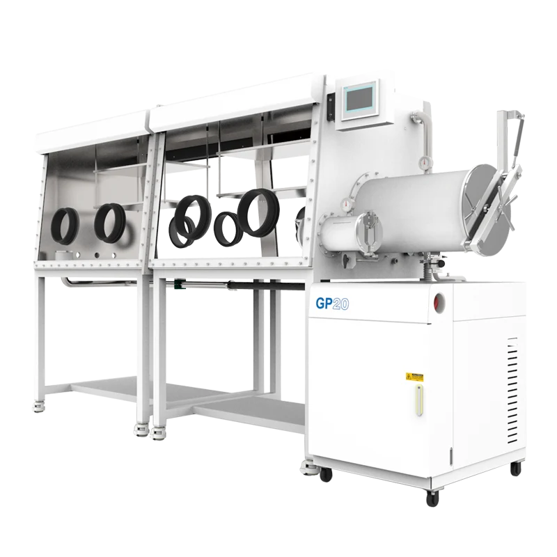
The TENCAN listing for the four-station double-sided split-type glove box with gas purification system describes a multi-station, two-sided, split-configuration enclosure paired with a purification system. That description is a starting point for configuration review, not a performance guarantee. A slow recovery can be normal after a large transfer, and a quick recovery can mask a small leak that is far from the analyzer. The sections below separate the physical causes so that a team can investigate the right part of the system before changing settings or purchasing hardware.
Why a transfer changes the O2 and H2O readings
The analyzer reports at its sampling point
An oxygen or moisture analyzer does not measure the whole box at once. It measures gas at a sensor or sample point, after that gas has traveled through a line and mixed with the loop. A leak near a glove port can therefore be invisible for a time while the local reading stays low. Conversely, a small amount of room air released close to the sample line can produce a sharp peak that looks larger than the average contamination in the box. Flow pattern, dead zones, sample-line length, and sensor response all shape the curve. Resolution is not the same as accuracy, and a reading in ppm or percent should not be compared with another reading unless the units, range, and calibration status are known.
Recovery is a balance between ingress and removal
During transfer, air enters through the open door, through the gloves, or as a film on the sample and container. The purifier removes oxygen and moisture, but only at the rate allowed by circulation, column condition, and contact with the reactive material. Materials can also release moisture or solvent vapor after the door is closed. The observed recovery time is the net result of these inputs and removal paths. If the ingress is large, the purifier is partly loaded, or the circulation is poorly distributed, recovery will be slow even when the box is working as designed.
Normal is a range, not a single number
Without a defined transfer test, slow is only an impression. A useful baseline records the reading before the door opens, the peak during transfer, the time to return to the pre-transfer band, and the stability over the next hour. The same test should be repeated with the same antechamber cycle, sample size, and workload. The relevant question is whether the system meets the agreed recovery pattern for the actual process, not whether it matches an advertisement.
What the four-station, double-sided, split layout adds
More access points mean more boundary
A four-station box gives more operators or more simultaneous tasks access to the controlled atmosphere. That is a workflow advantage, but every glove port, door, window seal, feedthrough, and split joint is part of the atmosphere boundary. More ports do not automatically mean more leakage; they mean more places to inspect and more opportunities for a glove to be damaged or a door to be left partly seated. The design only performs as well as its weakest seal and its operating discipline.
Station count is a workflow decision
Station count is not a quality rating. A four-station cabinet can support several operators or several parallel preparations, but it also adds glove ports, potential transfer events, and boundary area. If the process is normally run by one person, a four-station layout may add inspection and service access without adding throughput. If two sides are used for different tasks, the layout can separate clean preparation from sample handling. The useful specification is the number of active stations and the expected simultaneous transfers, not the port count alone.
Double-sided working changes traffic, not just space
A double-sided cabinet can reduce the distance people walk around the equipment and can separate preparation from inspection. It can also increase simultaneous door openings or transfers on two faces. If all stations are connected to one purification loop, a transfer on one side can affect the reading on the other. Confirm the zoning: whether all four stations share one atmosphere or whether the split design provides isolated sections. The product title alone does not establish that detail. The current arrangement drawing and valve schedule should.
Split construction puts attention on joints and service access
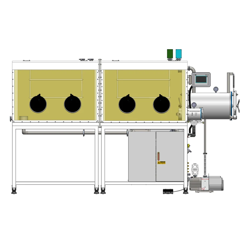
The term split-type indicates that the enclosure is organized in sections rather than as one undivided shell. This can help with transport, installation, or service access, but the joints, gaskets, and connections between sections become part of the leak path and the circulation path. Ask how the sections are sealed, how the purge or circulation is balanced across them, and how a joint is tested without disturbing the rest of the box. A split design is not a problem by itself; it is a set of interfaces that must be documented.
Where air and moisture enter during sample transfer
The transfer chamber is the first place to look
An antecamber or transfer chamber reduces exposure by allowing the sample to be evacuated and refilled before the inner door opens. The result depends on the chamber volume, the vacuum reached under actual load, the number of purge cycles, the gas used, and the door-seal condition. A pump's ultimate vacuum is not the same as the chamber pressure after a short cycle, and the box working pressure is a different quantity again. If the cycle is shortened to save time, or if a door seal is worn, the inner door can open with more air than the operator expects.
Gloves, ports, seals, and feedthroughs
Gloves are the most handled part of the boundary. A pinhole, a damaged cuff, a poor fit at the port, or a material that permeates the process solvent can all add contamination. Large gloves increase the volume that must be exchanged and can make movements less precise. O-rings and window seals age; feedthroughs and connectors introduce additional sealed joints. None of these items should be judged only by appearance. A planned inspection and replacement interval is more reliable than waiting for a reading to drift.
Valves and the vacuum path
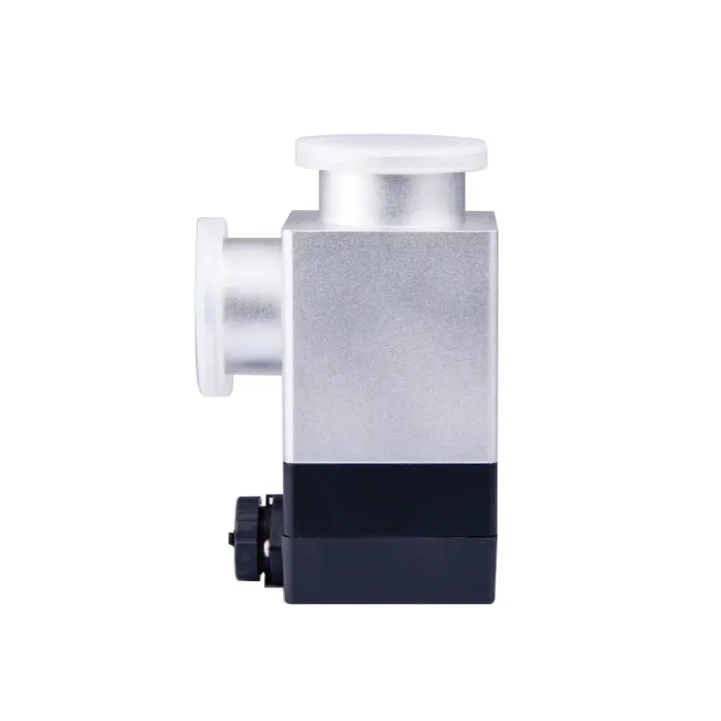
A pneumatic vacuum baffle valve is a vacuum-side component that can isolate part of the vacuum path under pneumatic control. Its job is isolation and routing, not purification. If a valve does not close cleanly, or if its actuator does not reach the commanded position, the transfer chamber may not reach the intended condition before the inner door opens. The supplied pneumatic vacuum baffle valve is an accessory category to evaluate against the box's flange standard, seal material, vacuum duty, and control interface; those details must come from the current accessory data, not from the product name. A valve cannot compensate for a worn door gasket or an exhausted purifier.
Purifier capacity, circulation, and analyzer behavior
The purifier is a finite system with a state
A gas purification system removes oxygen and moisture by passing the loop gas through reactive material. The material has capacity, and it may need regeneration or replacement. A system that recovers well when empty can recover slowly when the purifier is near the end of its useful interval or when a regeneration step has left it temporarily less effective. The presence of a purification system in the product name does not guarantee a particular outlet concentration. The meaningful information is the current column status, the regeneration history, the circulation flow, and the measured performance under a defined load.
Flow distribution matters as much as column size
Even a large purifier cannot correct a loop with poor flow distribution. If gas short-circuits between the blower and the return, or if a split section has a stagnant corner, contaminated gas may reach the analyzer slowly and leave the purifier underused. Baffles, ducting, and return points should be arranged so that all working zones participate in the loop. When a four-station box is operated with several doors and transfer chambers, the circulation design has to handle more than one path. Ask for a flow schematic, not only a purifier capacity.
The sensor can be the slowest part of the story
Some analyzers respond quickly; others need a stable sample flow, a warm-up period, or a calibration check. A sensor placed in a quiet corner may see a different concentration from one placed near the transfer door. A portable analyzer can help cross-check a fixed reading, but only if it is suitable for the gas and has been calibrated. Do not adjust the purifier or add purge cycles solely on the basis of one unexplained reading. Compare the trend, the sample point, and the instrument status.
Do not confuse purification with vacuum exchange
A stainless vacuum glove box that uses chamber evacuation and inert-gas refill is a different architecture from a continuously circulated purification box. The former can create a controlled atmosphere through exchange cycles; it should not be assumed to include a purifier. An acrylic isolator may be an isolating, micro-vacuum, or vacuum type depending on the model and wall thickness. The four-station split product discussed here is identified as having a gas purification system; the distinction matters when comparing recovery behavior. A vacuum-exchange box and a purification box can both show a slow reading after transfer, but the available removal mechanisms are not the same.
A diagnostic sequence before changing hardware
1. Define the event and record the baseline
Write down the starting O2 and H2O values, the analyzer range, the door or doors used, the duration of opening, the sample size and container, the antechamber cycle, and the time to recover. Keep the units consistent. A log of several transfers is more useful than a single screenshot. The aim is to separate a repeatable ingress event from a baseline drift.
What a useful transfer log contains
Record the date and time, the analyzer readings before and after transfer, the peak value, the recovery time, the door or chamber used, the cycle count, the sample or material identity, the operator notes, and any solvent or powder involved. Add a note when gloves are changed or when the purifier is regenerated. This turns a vague complaint into a set of comparable events. It also prevents a maintenance action from being credited or blamed without evidence.
2. Verify the transfer cycle and valve action
Check the antechamber door seal, the evacuation level reached, the purge gas supply, and the valve sequence. If a pneumatic valve is part of the circuit, confirm that it opens and closes fully and that its position feedback, if provided, agrees with the command. A valve that is slow or partly open can leave the transfer chamber in an intermediate state. The correct setpoints and timing belong in the current operating procedure for the specific system.
3. Separate a transfer response from a standing leak
If the box holds a stable baseline when no one is working, but rises after every transfer, the transfer path is the main suspect. If the baseline creeps upward overnight with the doors closed, look at gloves, seals, split joints, feedthroughs, and material outgassing. If the baseline falls only when the purifier is freshly regenerated, the purifier load or regeneration interval needs review. These patterns are different, and they call for different actions.
4. Inspect the boundary and the material load
Look for glove damage, gasket compression, door alignment, and loose fittings. Review what is being brought in: solvents, powders with high surface area, moist materials, and items with trapped air can all extend recovery. HEPA filtration captures particles; it does not remove water vapor or solvent vapor. A solvent adsorption device is not a substitute for the water and oxygen purifier. If the process uses solvents, the compatibility of gloves and seals and the need for vapor management should be discussed with the supplier.
5. Use trends and a simple matrix
A single high reading is not a diagnosis. A trend over several days, with notes on transfers and materials, is much more useful. The matrix below is a starting point for triage, not a substitute for the system's operating manual or a leak test.
| Observation | More likely area | Check |
|---|---|---|
| Baseline drifts with doors closed | Boundary or material load | Gloves, seals, split joints, feedthroughs, stored samples |
| Spike follows every transfer | Transfer ingress or cycle | Antechamber seal, vacuum level, purge count, valve action |
| Recovery slows over weeks | Purifier load or circulation | Column status, regeneration history, blower, flow path |
| One station is consistently different | Local flow or sensor placement | Sample point, dead zones, circulation balance |
| H2O rises more than O2 | Moisture load or glove permeation | Material handling, solvents, glove material |
Specifying a four-station purification box for the real workload
Specify recovery after a defined transfer
Instead of asking for the fastest possible recovery, define a test: transfer a stated sample mass or volume through a specified chamber, using a stated cycle, and record the time to return to an agreed band. The test should include the actual door or doors used in production. This makes the comparison between configurations meaningful. The four-station, double-sided, split-type product should be evaluated with the same workload it will see, not only with an empty box.
Ask for the atmosphere boundary and valve schedule
A current drawing should show the purification loop, blower, columns, antechambers, valves, analyzers, gloves, feedthroughs, and split joints. It should identify which sections can be isolated and how the transfer sequence is controlled. If the design includes a pneumatic vacuum baffle valve, the drawing should show its location and function. This is also where compatibility questions are answered: flange, seal, vacuum rating, actuator supply, and controls.
Keep the accessory decision separate from the purifier decision
A valve, a transfer chamber, a glove, and a purifier solve different problems. A larger purifier cannot fix a leaking door; a better glove cannot compensate for a wet sample; a valve cannot remove oxygen. Treat the accessory selection as an interface and reliability decision, and treat the purifier selection as a capacity and circulation decision. Both matter, but they should not be mixed into one specification.
Agree on acceptance checks
Useful checks include a baseline stability period, a defined transfer challenge, a recovery record, a leak check appropriate to the system, and confirmation of analyzer calibration. The acceptance values should be agreed for the actual process and units. Do not take a value from one test condition and apply it to every material or every shift. The operating procedure should state how the doors, valves, and analyzers are used so that the recovery data can be compared over time.
When the split layout is justified
A split layout may be justified when the room, doorway, or installation route cannot accept a single large enclosure, or when service access to one section is expected to be easier than access to the whole cabinet. It may also help when the process benefits from clearly separated work zones that remain connected to the same purification loop. These are layout and service arguments, not proof of better atmosphere performance. The recovery test and the boundary drawing should decide whether the split construction meets the need.
Before asking for a quotation, assemble the application facts: number of operators and stations, single- or double-sided access, whether the split layout is required for the room or installation, the largest and most frequent sample, the transfer chamber size and cycle, the materials and solvents involved, the required inert gas, the needed O2 and H2O range, the acceptable recovery time after a defined transfer, and the utilities and control interfaces available. Those facts will do more for the selection than a generic request for low oxygen and low moisture. A purification glove box is a system, and its recovery behavior is the visible result of its boundary, its purifier, its circulation, and its operating routine.
