
A two-station double-sided glove box with gas purification is specified when two people need to work in one inert atmosphere, or when samples must cross between sides without leaving the controlled volume. The layout is not just a larger single-station box. More glove ports, access faces, and transfer events all draw on the same gas volume, so transfer discipline and atmosphere monitoring become part of the configuration decision.
TENCAN's Two-Station Double-Sided Glove Box with Gas Purification System identifies the category clearly: two workstations, access from two sides, and integrated gas purification. Those features frame the selection, but they are not a full performance specification. Working dimensions, antechamber volume, leak rate, analyzer ranges, and utility requirements must be confirmed for the exact build. This guide focuses on the application questions behind that category: how transfers disturb a shared atmosphere, why purification and vacuum replacement are not interchangeable, and what to verify before purchase.
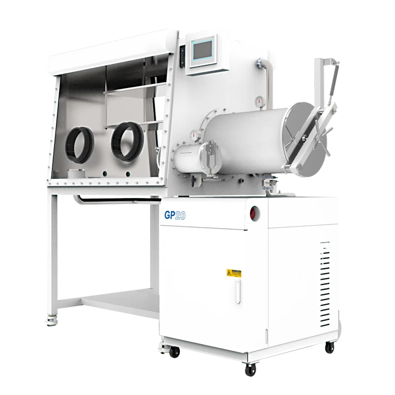
What the two-station, double-sided layout actually changes
Two stations are not simply two chairs at one box. Each station generally corresponds to a working position with glove access, and two-sided access may let operators work in parallel, serve different process steps, or shorten reach. The exact arrangement is a configuration detail; operators may face each other or use one side for preparation and the other for assembly. Review the layout drawing rather than inferring geometry from the name.
A shared atmosphere, not two independent chambers
Both stations use the same gas volume, sensors, and purification loop. If one operator opens an antechamber, introduces a solvent-bearing sample, or disturbs a glove port, the other station sees the result. A two-station box can improve throughput while making coordination more important. Scheduling heavy transfers so they do not overlap is often more effective than adding purifier capacity after the fact.
The shared volume also affects sizing. More ports and a larger chamber add surfaces, seals, and potential leak paths, while the purifier has to recover the working volume after each transfer. Two stations make sense when the work is genuinely parallel and transfer frequency is understood. They are a poor choice when the second station is added only for occasional use, because the extra volume still affects daily atmosphere management.
Throughput, ergonomics, and boundary paths
The benefit of a double-sided layout is often ergonomic: shorter reach, better sightlines, and fewer awkward turns. That matters for assemblies and sample holders that are hard to manipulate through one pair of gloves. The benefit disappears if two operators compete for the same work area or if the antechamber blocks one station. Map the sample path from entry to exit and count the handling steps before adding a station.
Every window, door, glove port, feedthrough, and flange is a boundary that must be sealed and maintained. A double-sided box is not automatically leakier than a single-sided one, but it has more joints to check. Ask for the leak-check method, pressure-holding procedure, and isolation-valve locations. Do not assume a larger box will hold an atmosphere simply because a purifier is attached.
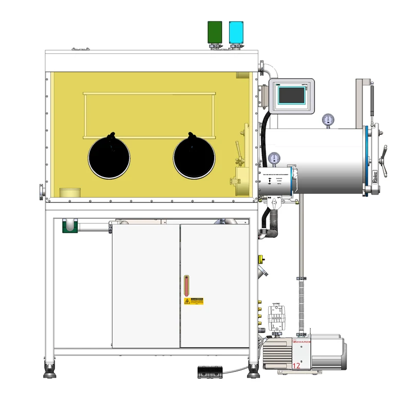
Purification, vacuum replacement, and regeneration are distinct functions
A gas purification system is a circulation loop. Box atmosphere is drawn through purification material, returned to the chamber, and monitored. Its job is to remove water and oxygen that enter through small leaks, glove permeation, or transfers, and to restore the working atmosphere between events. It does not create a barrier at the antechamber door, and it does not stop air from entering during a transfer.
Vacuum replacement is a batch operation. A sealed volume is evacuated and refilled with inert gas, often more than once, to reduce the air fraction before it is connected to the main chamber. It works well on small, isolated transfer volumes. It is not continuous purification and cannot maintain the main chamber on its own. A box may use both functions, but they answer different questions: purification manages the working volume; vacuum and backfill manage the transfer path.
Regeneration is maintenance, not a purge
Purification material has finite capacity and must be regenerated or replaced according to the manufacturer's procedure. Regeneration has its own gas supply, valve alignment, and temperature program. It is not a routine way to clean the working volume, and it should not be confused with purging an antechamber. If the process releases solvents or other species the purification material does not handle, regeneration will not solve the compatibility problem.
| Function | What it contributes | What it cannot do |
|---|---|---|
| Continuous purification loop | Circulates chamber gas through purification material and supports recovery after small disturbances | Prevent air ingress during an open transfer or replace a proper antechamber cycle |
| Vacuum and inert backfill | Reduces the air fraction in an isolated transfer volume before it is opened to the chamber | Continuously remove water and oxygen from the main chamber |
| Purification-material regeneration | Restores capacity in the purifier according to the manufacturer's procedure | Clean the working volume or compensate for an incompatible solvent load |
| HEPA particle filtration, when specified | Captures particles in the gas path | Remove water vapor, oxygen, or solvent vapor |
The categories are often blurred in specifications. A purification column is not a particle filter. A HEPA filter, where specified, captures particles but not water, oxygen, or solvent vapor. A vacuum pump removes gas from a volume; it does not purify the gas. Keeping those functions separate makes it easier to ask the right questions about the two-station box and its accessories.
Sample transfer is the real atmosphere test
Most disturbances begin at a door. A sample, tool, or container enters the antechamber with air attached to its surfaces and trapped in its packaging. The cycle reduces that air, but the load still carries a boundary layer, porosity, or dead volume. Once the inner door opens, remaining air and any outgassing species mix into the main chamber. The purifier then works to restore the baseline. Recovery time depends on chamber volume, load, purifier capacity, valve sequence, and the condition of gloves and seals.
This is why transfer discipline matters more than the station count suggests. A small sample passed quickly may cause a barely visible excursion. A porous load, a solvent-wet part, or a large container with trapped air can cause a much larger one. If both stations transfer at the same time, the disturbances add. The atmosphere may recover, but the curve becomes harder to interpret and a sensitive sample in the other station may be exposed.
Antechamber volume and valve sequencing
The antechamber should accept the largest routine item without forced disassembly. A very small chamber reduces the volume to be exchanged but may limit tooling and containers. A larger one accepts more but uses more gas and a longer exchange per cycle. Base the choice on the real load list, not on the largest object anyone can imagine. Valve sequencing also matters: evacuating too quickly can disturb a powder, and backfilling before a stable vacuum leaves more air than expected.
Where a KF vacuum clamp fits
Vacuum lines and transfer connections need secure joints. A KF Vacuum Clamp holds a KF flanged connection together; it does not create vacuum, remove water or oxygen, or substitute for a seal. Its relevance is at the vacuum boundary, such as an antechamber line or pump connection. The clamp must match the flange size, seal, and line conditions, and the joint must be assembled correctly. A mismatched or damaged seal can defeat an otherwise sound vacuum system.
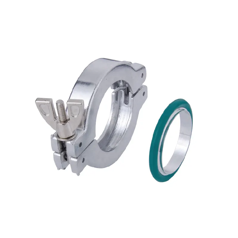
Because the clamp is simple, it is easy to overlook. Ask which KF connections are present, what seal material is appropriate, and whether the clamp is intended for the line's service. The answer should come from current product information and the system drawing. Do not assume a clamp sold for one flange series will fit another, and do not treat it as a purification component.
Two operators, one recovery curve
Treat transfers as shared events. If one station is about to introduce a large load, the other should not open a door or change a glove at the same time. A brief coordination step prevents overlapping disturbances and makes the analyzer response easier to interpret. For repeated work, log the load type, cycle used, starting readings, and time to return to baseline. Without a baseline, every excursion looks like a fault when it may simply reflect a larger transfer.
Reading oxygen and moisture without overclaiming
An analyzer measures the atmosphere at its sensing point. It does not purify the atmosphere, and it does not prove that every part of the chamber has the same concentration. Oxygen and water are separate measurements with separate sensor behavior. A low oxygen reading does not automatically mean moisture is under control, and a stable moisture reading does not prove oxygen is low.
Resolution and accuracy are different. A display may show small increments, but measurement uncertainty depends on the sensor, range, calibration, and sampling arrangement. A headline number without test conditions is not a reliable selection criterion. If a supplier states an achievable value, ask where it was measured, over what period, with what load, and after what stabilization time.
Placement, calibration, and response time
Placement changes what a reading means. A sensor near the return line may respond differently from one in the working zone. Calibration establishes traceability but does not eliminate drift between services. When a reading is suspect, check calibration status, sample flow, sensor connection, and reference gas first. Response time is a system property that includes the sensor, sampling line, chamber mixing, and purification loop.
A slow response after transfer can come from a large load, a partly open valve, a glove leak, an aged seal, or a purifier approaching the end of its capacity. It can also come from a sensor that is slower than the event. Do not diagnose a failed purifier from one recovery curve. Compare the event with the baseline and check the simple boundary conditions first.
A stable reading shows that the measured variable is not changing at that moment. It does not prove the box is leak-free, that the next transfer will be uneventful, or that a solvent will not damage the purification material. It also does not turn an inert atmosphere into a sterile environment. Low water and oxygen, particle control, solvent management, and sample cleanliness each need their own solution.
Configuration choices that matter more than the model number
Once the category is fixed, configuration details determine whether the box supports the process. The table below is a starting point for the supplier conversation. It does not assume a particular build; it identifies items that should be explicit in the quotation and drawings.
| Decision | Why it matters | What to confirm |
|---|---|---|
| Station spacing and glove-port positions | Determines reach, sightlines, and whether two operators can work without collision | Port size, spacing, glove material, and left- or right-hand access |
| Antechamber size and count | Sets the transfer bottleneck and the volume that must be exchanged | Internal dimensions, door clearance, pump connection, and valve sequence |
| Chamber construction and access sides | Affects usable workspace, service access, and the number of sealed boundaries | Working dimensions, window arrangement, and leak-check method |
| Analyzer package | Defines what can be verified and how recovery is judged | Measured species, range, calibration, sensor location, and alarm logic |
| Solvent and particle controls | Protects the purification material and the working volume | Solvent compatibility, trap placement, filter type, and replacement access |
| Feedthroughs and service ports | Allows instruments, power, and vacuum lines to cross the boundary | Connector type, sealing, electrical rating, and KF flange size |
Accessories should be evaluated in the same way. A vacuum clamp, feedthrough, or replacement glove is not an upgrade by itself. It is useful only if it matches the port, line, and process. Treat the main product page as the system anchor and accessory pages as interface details. If compatibility is not stated, ask for it in writing rather than inferring it from a photograph.
Purification capacity and utility planning
The purification system needs space, power, and possibly a regeneration gas supply and exhaust route. Those requirements belong in the facility plan, not in a late installation conversation. A two-station box may have more working volume and more frequent transfers than a single-station unit, which can affect how often the purifier is challenged. Exact capacity and utility data must come from current product information.
Allow access for filter changes, leak checks, and analyzer calibration. A purifier that is difficult to reach may be neglected, and a control cabinet in a cramped area makes routine checks inconvenient. These details determine whether atmosphere control is actually maintained.
Materials, solvents, and the limits of inert atmosphere
An inert atmosphere is not universal protection. It lowers reactive gas concentrations, but it does not make every material stable or remove every contaminant. Solvent vapor can load purification material and affect other samples in the shared chamber. Particles can move through the gas path and settle on surfaces. Solvent adsorption is separate from water and oxygen purification, and it does not replace the purification loop.
Powder handling needs particular care because powders disperse, settle into seals, and contaminate the working area. Keep the material contained, minimize open handling, and use a cleaning method compatible with the box. This is a contamination-control issue, not a reason to introduce unrelated powder-processing equipment. The box provides a controlled atmosphere around the material; it is not a mill or blender.
Check gas compatibility, not just inert
The working gas, control gas, and regeneration gas may differ, and each has its own purity and supply requirements. Confirm which gases the configuration is intended to use and what grade is required. A generic inert-gas connection may not be sufficient. The same caution applies to samples: a gas that is inert toward one material may react with another, and a solvent acceptable at room temperature may behave differently during processing.
The two-station layout increases the chance of cross-contamination because two processes share one atmosphere. If one station uses a volatile material, protect the other by procedure, isolation, or a dedicated trap. A purification system is not a substitute for segregation when the chemistry requires segregation.
A practical specification and acceptance checklist
Before requesting a quotation, assemble the information that changes the design: materials, largest and heaviest load, transfers per shift, whether two operators work simultaneously, solvents or volatile species, required oxygen and water levels, instruments crossing the boundary, and available utilities. Add floor space and maintenance access. This is more useful than asking for a standard two-station box because it exposes the real trade-offs.
At acceptance, verify the system as an integrated unit. Start with a clean, empty box and record the baseline under the intended working gas. Check door seals, glove ports, feedthroughs, and vacuum joints. Perform a controlled empty transfer and observe the analyzer response, then repeat with a representative load. The difference in recovery time shows how the box behaves in the work it will actually do.
- Working dimensions and glove-port positions against the intended tasks.
- Antechamber volume, door clearance, and vacuum source for the largest routine load.
- Analyzer species, ranges, calibration, and sensor locations.
- Purification capacity, regeneration requirements, and utility connections for the exact build.
- Leak-check method and pressure-holding procedure, with units and test conditions.
- Glove material and thickness against samples, solvents, and dexterity needs.
- KF flange sizes, seal materials, and clamp compatibility for every vacuum connection.
- Solvent and particle controls, and whether they are independent of purification.
- Feedthrough types, ratings, and sealing for instruments inside the box.
- Training, operating procedure, and service access.
The final choice should be judged against the transfer plan, not a feature count. A two-station double-sided purification box fits when two working positions genuinely reduce handling, when the antechamber and purification strategy match the load, and when operators can coordinate use of a shared atmosphere. It fits poorly when the second station adds volume and ports without removing steps. The same logic applies to accessories: a clamp, feedthrough, or filter is valuable only when its interface and function are understood.
Compare the proposed layout with a week of real transfers. Identify the busiest moment, the largest load, and the most sensitive sample. Then ask which part of the system protects that moment: the antechamber cycle, purification loop, analyzer, glove, or procedure. If the answer is clear, the configuration is probably aligned with the work. If not, the missing detail belongs in the specification before the box is ordered.
