
Two questions get tangled together whenever atmosphere equipment is specified. How clean must the internal atmosphere be, and how does the enclosure reach and then hold that condition? The GBV-2 stainless steel vacuum glove box answers the second question in a particular way — evacuation followed by inert gas replacement — and that choice defines what the platform is good at, what it cannot promise, and which accessories are worth adding at order time.
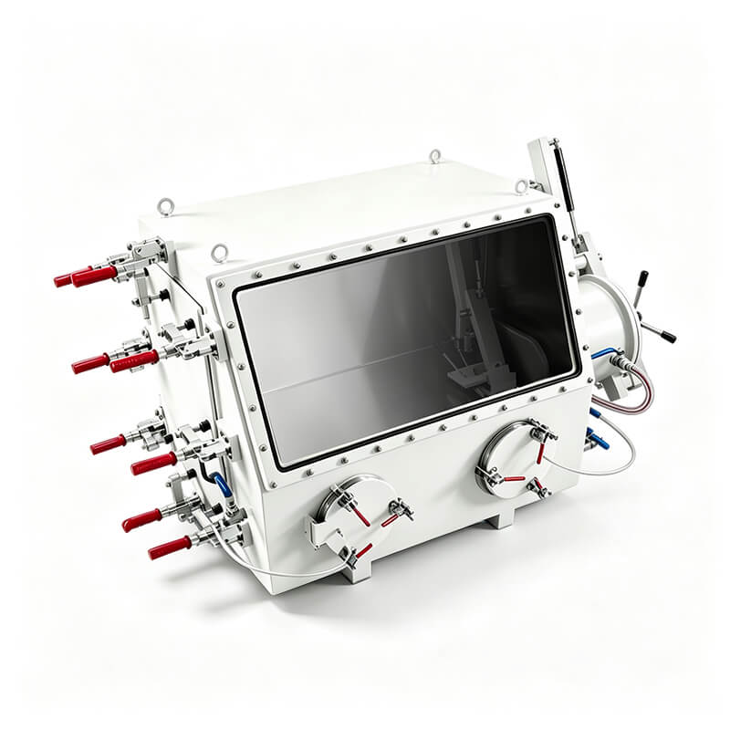
The discussion below moves from mechanism to configuration to verification: how a replacement cycle actually lowers water and oxygen, how chamber size and transfer hardware change the atmosphere budget, where electrical interfaces such as a KF40 test lead feedthrough fit, and which symptoms usually mean a parameter needs to be confirmed rather than a component replaced.
Why the GBV-2 Starts From a Different Premise
A vacuum glove box and a purifying glove box are both sealed enclosures with gloves, but they are built around different recovery mechanisms. A purifying box runs a closed loop: gas is drawn from the chamber, passed through purification material that removes water and oxygen, and returned. The enclosure is expected to stay closed for long periods, and the atmosphere is continuously managed. A vacuum box such as the GBV-2 reaches its working condition by pumping the chamber down and refilling it with inert gas, repeating the cycle as needed. Nothing in that description assumes a continuously regenerated purification loop. The assumptions are narrower and more concrete: the enclosure seals, the air is removed, and the inert gas you introduce is the atmosphere you keep.
That difference is not a question of quality. It is a question of what the box can guarantee and what the operator has to manage. A vacuum and replacement platform suits work where samples are processed and then removed, where the number of atmosphere exchanges is modest, and where the enclosure is opened deliberately rather than left running for weeks. Continuous purification is the better answer when the atmosphere itself is a process variable that must be held inside a narrow band while many transfers happen, or when a sample must sit under inert gas for days at a time.
TENCAN's GBV-series documentation is explicit on this point: the vacuum box forms its controlled environment through evacuation and inert gas replacement, and it is a different product category from a system with an integrated purification loop. Reading the specification with that in mind prevents two recurring mistakes — assuming a vacuum box carries the ppm-level purification columns of another product family, and assuming that a purifying box can be swapped for a vacuum box wherever inert gas is mentioned.
What "inert atmosphere" means in a vacuum box
In the vacuum-box workflow, the atmosphere is whatever gas remains after the replacement cycle. If the chamber is pumped to a low absolute pressure and then refilled with dry nitrogen or argon, the residual air is reduced twice: once by removing gas during pumping, and once by adding replacement gas. Repeat the cycle and the residual fraction falls further. The practical limit is set by the vacuum the pump and chamber can actually reach, the purity of the refill gas, the leak rate of the seals, and how much air enters each time the box is opened or a transfer takes place.
This is why the useful question is not "is it inert?" but "how many exchanges, at what pressure, with what gas, and how tightly does the enclosure hold?" Those four parameters decide whether a vacuum box is adequate for a given sample.
What a purifying system adds, and what it does not remove
A system with a purification loop adds active removal: water and oxygen that enter the box are captured rather than merely diluted. That supports long campaigns, frequent transfers, and processes where the atmosphere must recover quickly after every opening. It also adds components with their own maintenance logic — purification columns, circulation, regeneration, and the monitoring that tells you when the purification material is spent.
Neither approach removes the need for good sealing, clean transfer practice, or appropriate gloves. Both fail for the same underlying reason: air enters and nobody notices until a sample changes.
How a Replacement Cycle Reduces Water and Oxygen
Take a chamber at atmospheric pressure containing some fraction of air. Pump it down to a lower absolute pressure and, assuming the gas is reasonably well mixed and the pump draws from the whole chamber, the absolute quantity of air remaining scales roughly with the ratio of final to initial pressure. Refilling to atmospheric pressure with inert gas restores the volume but not the air: the same absolute quantity of air is now spread through the full chamber, so its concentration falls again by a similar ratio. In practice the process is imperfect. Mixing is uneven, dead volumes behind internal structures and in corners hold gas longer, and the refill gas itself carries some moisture and oxygen.
This is why a repeating cycle is normal procedure rather than evidence of a problem. The first pull brings the chamber down from atmospheric; the refill dilutes what remains; the next pull removes most of that remainder. The decision that matters is where to stop, and that decision should come from the sample specification, not from a display reading taken thirty seconds after refill.
Refill gas quality is part of the atmosphere
A cycle can only be as good as the gas used to refill it. Refill gas supplied at a lower purity, or delivered through lines and regulators that adsorb and release moisture, adds water back at the end of every cycle. Line material, line length, and whether the line is purged before use all matter. If the process is sensitive, state the required gas purity and the delivery arrangement, and confirm that the regulator and any flexible hose are compatible with that requirement.
Pressure, leak rate, oxygen and moisture are four different numbers
They are often quoted in the same sentence, which is where confusion begins.
- Chamber working pressure describes the pressure range the enclosure is designed to operate within. It is not an oxygen specification.
- Transfer chamber vacuum describes the pressure reached inside a small airlock during a transfer cycle, not the main chamber.
- Pump ultimate vacuum is a property of the pump, measured at the pump inlet under defined conditions. It is not the pressure your chamber will reach, because conductance and outgassing intervene.
- Leak rate describes how quickly pressure or composition drifts when nothing is being done. It is the number that decides how stable the atmosphere stays between cycles.
- Oxygen and moisture readings describe the gas at the point where the sensor sits, as interpreted by a specific instrument with a specific calibration.
Blurring these values is the most common source of unrealistic expectations. A pump with a very low ultimate vacuum does not by itself produce a low-oxygen chamber, and a low oxygen reading taken immediately after a refill does not describe the atmosphere an hour later. Keep the unit and the object attached to each value, and a specification becomes readable.
Mixing and settling before you sample
Dilution is only as uniform as the gas movement inside the chamber. If the configuration provides a means of circulating or fanning gas during refill, the fresh gas distributes faster and the reading stabilizes sooner. If it does not, allow the chamber to settle before trusting a measurement, and place the sample point where it sees the working volume rather than a stagnant pocket. Sampling immediately after refill usually reports the refill gas, not the working atmosphere.
Configuration Decisions Inside the GBV-2 Family
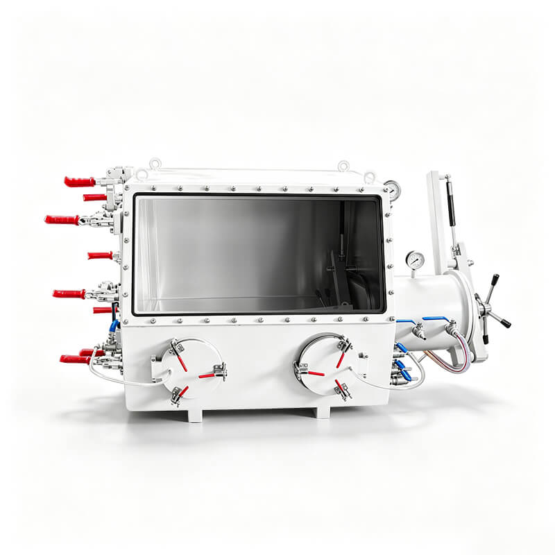
Within a stainless steel vacuum glove box line, most of the variation that matters is structural. Chamber size, glove port count and spacing, viewing arrangements, internal fixtures, and the presence or absence of a transfer airlock change how the box is used far more than a model number suggests.
Chamber volume and glove port layout
A larger chamber holds more work at once and reduces how often the box must be opened. It also contains more dead volume, so each replacement cycle moves more gas and takes longer to complete. A smaller chamber cycles faster and recovers more predictably, but forces more transfers when a process involves several steps or a long assembly. Glove port spacing decides whether two people can work without colliding, and whether a long sample can be turned, mounted, or wired without one hand fighting the other.
The habit worth forming is to size the chamber around the largest single operation — the assembly, the fixture, the cell stack, the deposition holder — and then ask whether the number of operators justifies additional working positions. Adding positions later is not a matter of drilling a hole; it changes the enclosure.
Single and multiple working positions
Layout affects atmosphere as well as ergonomics. A single-position box keeps the working volume small, which shortens each cycle and limits how much air a door opening introduces. Multiple positions widen the chamber, which is convenient for two-operator work and for staging long processes, but also raises the gas volume that must be exchanged and the number of seals and ports that can leak. Neither layout is inherently better; the layout follows the workflow. If your process alternates between a preparation step and an assembly step in the same session, a wider chamber can reduce door openings, which is a real atmosphere benefit.
Viewing, lighting and internal fixtures
Visibility is a working condition, not a convenience. A window adequate for inspection may be inadequate for aligning a small part with tweezers at the end of a glove. If the process involves inspection under magnification, soldering, or fine wiring, plan how light and sight lines reach the work area, and confirm what internal shelving, rails, or supports the configuration provides. Materials used inside the chamber matter too: polymers, tapes, and adhesives can release moisture and solvent vapors, adding to the load the atmosphere has to tolerate.
Transfer airlocks and what they protect
If the configuration includes an antechamber or transfer airlock, that small volume is where most of the atmosphere discipline actually happens. A sample goes into the airlock, the airlock is evacuated and refilled, and only then is the inner door opened. Done this way, the main chamber sees a small, controlled exchange instead of a full room-air intrusion.
Two numbers belong to the airlock and not to the chamber: how small its volume is, and how low it can be pumped. A small airlock that reaches a good vacuum removes more air per cycle than a large one and does so using less gas. This is why transfer discipline often improves atmosphere stability more than any change to the main chamber. If your configuration has no transfer airlock, every item enters through the main door or a glove port, and the replacement budget rises accordingly — a good reason to batch transfers deliberately.
Electrical Measurement Inside a Sealed Box: Feedthroughs
Most atmosphere-sensitive work eventually needs a wire: a thermocouple, a resistance measurement, a cell under test, a sensor, a small heater. Passing a conductor through the enclosure wall is where a sealed box turns into an interface problem.
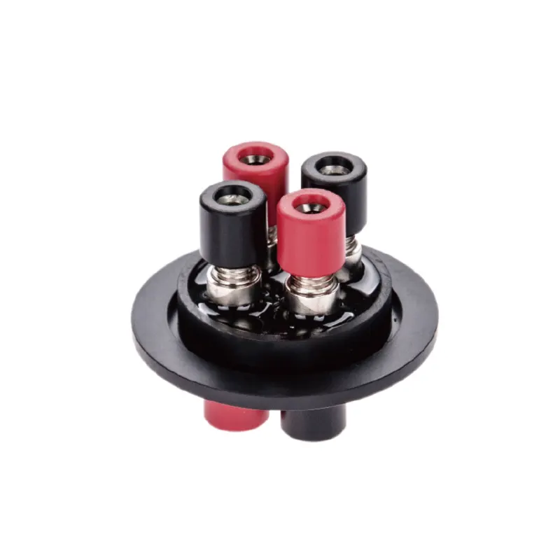
The KF40 electrical test lead feedthrough belongs to exactly this category. It carries test leads through a chamber wall on a KF40 (NW40) flange interface, so the electrical path enters the box through a standard vacuum connection rather than through a modified door seal or a cable routed past a gasket.
Why the flange standard matters
KF fittings are a common vacuum interface: a flange, a centering ring with an elastomer seal, and a clamp. Because the interface is standardized, a feedthrough can be added to a port plate, replaced with a blank when it is not needed, or moved to another position without fabricating a new wall. Confirm, however, that your enclosure or its accessory plate actually presents a KF40 port, and whether the centering ring, clamp, and blanking plate are part of the order. A KF40 feedthrough is not a universal fit; it is a fit for a KF40 port.
What to specify before ordering
- Conductor count and type — how many leads are needed, and whether they are plain wire, shielded, or thermocouple alloy pairs. A shielded pair behaves very differently from two separate wires, especially for low-level signals.
- Current and voltage of the test — the conductor and insulation must suit the load, including inrush if you are switching a heater or a small motor.
- Insulation and seal compatibility — solvents, acids, and reactive vapors attack some materials. State what will be present inside the chamber.
- Termination on each side — what the leads end in, inside and outside, and whether connectors or bare ends are required.
- Shielding and grounding path — where the shield terminates, and whether the flange is part of the electrical ground. A floating shield can be worse than no shield at all.
- Leak integrity after installation — a feedthrough is a sealed joint only if it is installed and checked as one. Plan a leak test after fitting.
On its own, a feedthrough does not extend the atmosphere capability of the box; it adds an access point. Its value is that it lets you measure inside the enclosure instead of removing the sample to measure it, which for an air-sensitive sample is often the entire point of the experiment.
Feedthroughs are not the only interface to plan
Gas lines, thermocouple wells, mechanical shafts, and optical windows follow the same logic: a defined flange, a defined seal, and a defined leak-check procedure. Grouping those interfaces at order time avoids a sequence of custom modifications later, each of which adds another potential leak path and another object to verify.
Symptoms That Point to a Parameter, Not a Part
When atmosphere work goes wrong, the failure is usually described as a symptom rather than a measurement. The useful response is to identify which parameter the symptom implicates, verify it, and only then change hardware. The possibilities below are hypotheses to check, not diagnoses of any particular installation.
The oxygen reading recovers slowly after a transfer
Slow recovery after opening an airlock or a door is usually a statement about the air that entered. Candidates worth checking: whether the airlock cycle was completed before the inner door opened; whether items carried in on gloves displaced air into the chamber; whether the sample point mixes poorly with the rest of the chamber; whether the analyzer's own response time is being read as the box's recovery time; and whether seals at gloves, port plates, and doors hold under the pressure difference actually applied. A leak that is negligible at rest can become significant under the pressure swings of a replacement cycle.
A sample changes despite purging
If a sample degrades even though the cycle procedure was followed, the atmosphere may never have reached the target at the sample surface. Consider the route the sample travelled: time spent in the airlock, time inside a transfer container, whether that container was itself purged, and whether the sample was warm enough to outgas on entry. Solvent residues and adsorbed water on tools and fixtures contribute as well. Materials inside the chamber — tapes, polymers, printed labels — can release both moisture and organic vapors. A solvent trap addresses only the organic fraction; it does not remove water and oxygen, and it does not convert a replacement-cycle enclosure into a purifying system.
Pump-down takes longer than it used to
A slower pump-down is a comparison, not an absolute: what matters is the change from the installation's own baseline. Possible contributors include a partially loaded line, a hose long or narrow enough to dominate conductance, condensable vapors from solvents, outgassing from new internal fixturing, seal condition, and the range of the gauge used to judge pressure. Check also whether the value you are reading is chamber pressure or pump-inlet pressure; the two can differ by more than expected.
Readings that disagree with each other
When moisture and oxygen readings tell different stories, the disagreement is often about location, calibration, or time rather than about the atmosphere. Two sensors at different points in the chamber can legitimately differ during a cycle. One sensor can be due for calibration. One reading can be taken before the chamber has settled. Record readings with their timestamp, location, and instrument so that a trend can be distinguished from an excursion.
Matching the Enclosure to the Application
The application decides which atmosphere strategy is worth paying for. The categories below are typical contexts where inert handling matters; each still needs its own target stated as a range rather than as a single prohibited number. Inert protection is not the same as sterility, a cleanroom classification, biosafety containment, or hazardous-material certification. It also is not a claim that every gas is inert toward every sample — argon, nitrogen, and helium differ in density, purity, and reactivity, and some materials react with nitrogen.
Alkali metals, batteries and solid-state materials
Lithium metal, sodium, and many solid electrolyte powders and laminates are handled inertly because water and oxygen react with them. Here the atmosphere question is combined with a mechanical one: cutting, pressing, stacking, and sealing a cell. If the process is a sequence of discrete steps ending in a seal, a vacuum box with disciplined transfer routines can be workable. If the process involves repeated opening over hours, long-duration electrochemical testing inside the enclosure, or frequent sample exchange, the case for a continuously purifying system strengthens.
Perovskite, OLED and semiconductor-adjacent work
These processes are usually sensitive to both moisture and oxygen, and they often involve solvents. Solvent vapor is the complication: it loads the enclosure and is not removed by a desiccant or a particle filter. Where solvents are present, plan ventilation or trapping explicitly and confirm material compatibility for gloves, seals, and windows.
Air-sensitive chemistry and organometallics
Reagent handling often means small quantities under careful procedure, which suits a vacuum and replacement approach provided the material is kept closed and transfers are batched. Pyrophoric and water-reactive materials bring their own safety requirements, which sit outside the scope of the enclosure specification and must be addressed separately by the responsible safety authority.
Powder handling and additive feedstock
Powders are handled in a glove box for two different reasons: the material is air-sensitive, or the operator needs protection from the powder. In the first case, the atmosphere target is set by the material. In the second, the concern is containment and filtration, which is a separate problem — a HEPA filter controls particles, not water or oxygen. Do not let a filtration specification stand in for an atmosphere specification, or the reverse.
| Question | Vacuum replacement (GBV-2 type) | Continuous purification |
|---|---|---|
| How the atmosphere is established | Evacuation followed by inert gas refill, repeated as needed | Closed-loop circulation through purification material |
| Recovery after opening | Depends on a further replacement cycle | Handled by the loop, within its capacity |
| Best suited to | Batch work, deliberate transfers, moderate sensitivity | Long campaigns, frequent transfers, sustained atmosphere targets |
| Parameters to confirm | Sealing, cycle count, refill gas quality, transfer hardware | Purification capacity, regeneration cycle, monitoring |
Configuration Checklist Before You Order
Whether the platform ends up being a vacuum box, a purifying system, or a vacuum box with a small number of added interfaces, a supplier's recommendation is only as good as the inputs behind it. The list below is a practical set of items to have ready, and it doubles as a checklist to run against a quotation.
- Sample or process: what the material is, and what it reacts with.
- Atmosphere target expressed as a range at a defined measurement point, plus how long an excursion is acceptable.
- Transfer frequency, item size, and the largest object that must pass into the chamber.
- Number of simultaneous operators, and the fixtures or instruments that will live inside permanently.
- Whether solvents, acids, or reactive vapors will be present, and in what quantity.
- Electrical interfaces required: signal type, conductor count, current and voltage, shielding, and termination.
- Flange standards available on the enclosure or accessory plate, and whether clamps and blanking plates are included.
- Pump and gauge expectations, and how pressures will be measured, recorded, and compared over time.
- Analyzer requirements: range, resolution, calibration interval, and the location of the sample point.
- Whether the atmosphere must be held between sessions or only during them — often the deciding question between replacement cycling and continuous purification.
When the box, the transfer hardware, and the interfaces are specified together, the result is easier to operate and easier to verify. Start from the GBV-2 stainless steel vacuum glove box platform and treat every added port, filter, and feedthrough as a change to the atmosphere budget that should be justified by one specific operation. That way, the enclosure you receive matches the work you actually do, and the numbers you record afterwards mean something.
