
When a purified glove box is working normally, oxygen and moisture readings sit at a low baseline and move only slightly when a sample goes in or out. When they do move, the useful question is not the number on the display but how quickly the atmosphere returns to where it was. Engineers call this "recovery," and slow recovery is one of the most common reasons a two-station single-sided glove box with a gas purification system gets adjusted, investigated, or blamed. Recovery is a system property: it depends on the circulation loop, the purification column, the internal volume, the way samples are transferred, and the instrument doing the measuring. This article examines why oxygen and moisture can take a long time to settle in a two-station single-sided purification box, and which parameters should be confirmed before any hardware is replaced.
Slow Recovery Is Not the Same as a High Reading
Two measurements are often mixed together. The first is the steady-state level: what the analyzer shows after several hours with no transfers, no new materials and no door or antechamber activity. The second is recovery rate: the slope of the reading after a defined disturbance, such as one antechamber cycle or one sample exchange. A glove box can hold an acceptable baseline and still recover slowly, and it can recover quickly and still sit higher than expected. These two conditions usually point to different causes, so it is worth deciding which one is actually being observed before changing anything.
In a two-station, single-sided box the distinction matters more than in a single-station enclosure, because both working positions share one atmosphere and one purification loop. A disturbance introduced at one station is visible at the other. The two stations are not independent mini-boxes; they are two access points on the same internal volume. Slow recovery therefore describes the loop's ability to remove the water and oxygen that were just added, relative to the volume it has to clean. The size of that volume, the rate at which gas circulates through the purification media, and the condition of those media all sit on the same side of the balance.
How a Closed-Loop Purification Glove Box Is Built
A continuously purified glove box is a closed circuit. The chamber atmosphere is pulled through a circulation path, passed through purification media that remove water and oxygen, and returned to the working volume. Sensors monitor the atmosphere, either in the loop or in the chamber itself. A control system manages the circulation, the regeneration of the purification media, and the pressure inside the box. The antechamber, if present, is a separate small volume that allows materials to enter and leave without opening the main chamber to room air.
The purification media are two different functions in one column or in separate columns. Water is removed by adsorption on a desiccant. Oxygen is removed by a catalytic or chemisorption route, typically involving a copper-based material that must be regenerated periodically. Regeneration is not the same as normal operation: it uses heat and a gas stream to drive off the collected water and to reduce the oxygen-removal medium back to its active form. During regeneration, that column is offline, which is why larger systems sometimes use two columns so the loop keeps running.
Startup and refilling follow the same logic. Before the loop can hold a baseline, the chamber has to be brought from air to an inert atmosphere through purging, evacuation, or a combination of both. Once the loop is closed, the purification media do the fine work of removing the residual water and oxygen that the initial exchange could not remove. This is one reason two boxes with identical purification hardware can behave differently: the quality of the initial exchange and the tightness of the enclosure set the starting point for everything that follows.
Pressure management is part of the same system. A slight positive pressure relative to the room reduces the driving force for air to seep inward, while still keeping the box within its design limits. Pressure that is too high stresses gloves, seals and viewports; pressure that wanders may indicate a leak, a blocked path, or a control issue. The pressure gauge and the oxygen and moisture readings are complementary, not interchangeable.
This is the key architectural contrast with a vacuum or atmosphere-replacement enclosure. A replacement-type box creates a controlled atmosphere by repeatedly evacuating and refilling with inert gas. It can be very effective for storage and for certain operations, but it does not continuously circulate and purify. It therefore has no recovery curve in the same sense — the atmosphere is what the last fill left behind. Continuous purification and gas replacement solve different problems, and neither is automatically "better"; the choice depends on how often the box is used, what materials are handled, and how tightly the oxygen and moisture levels must be held.
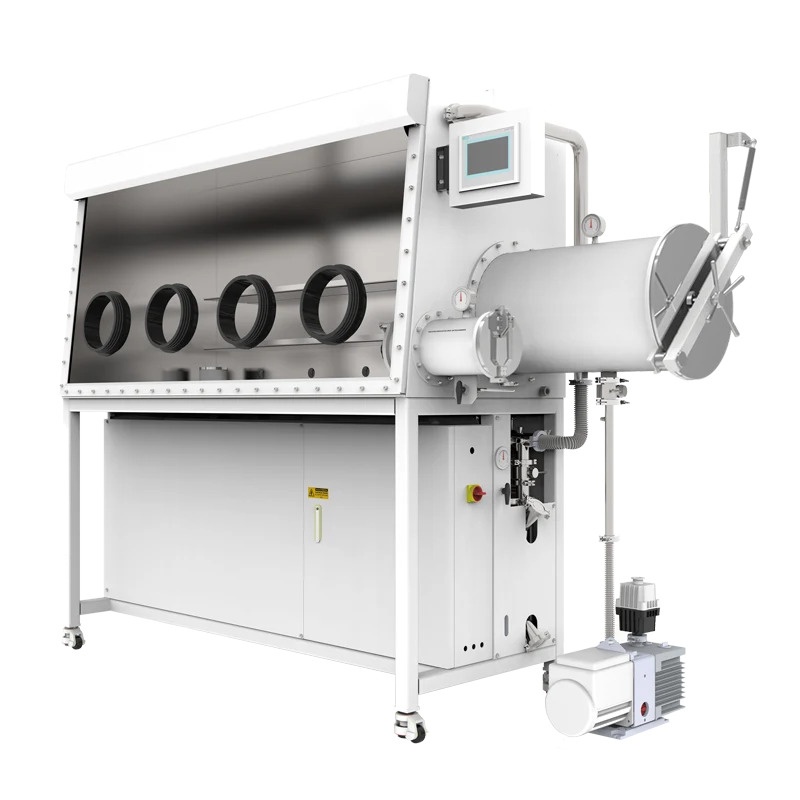
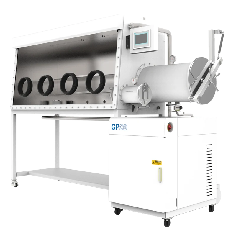
The two-station, single-sided layout adds a workflow dimension. Single-sided means operators work from one face of the box; two-station means two pairs of glove ports share that face and the same internal atmosphere. This configuration suits a bench where one or two people work side by side, and it keeps the footprint narrower than a double-sided box of similar working length. The trade-off is that the purification system is shared, and its capacity must be matched to the total volume and to the rate at which the box is disturbed — not to a single station. The two-station single-sided glove box with gas purification system is a useful reference point for how that architecture is packaged.
Where Oxygen and Moisture Enter the System
Understanding recovery starts with understanding the load. In a well-sealed box, most of the water and oxygen seen by the purification loop comes from predictable, routine events rather than from a dramatic failure.
- Antechamber transfers. Every cycle brings in the atmosphere that clings to the sample, its container, the antechamber walls and the operator's gloves. Purge or vacuum cycles reduce this load but cannot remove all of it.
- Materials and containers. Cardboard, paper, tapes, many polymers and solvents release water and oxygen-containing species. Powders are a special case: a fine powder can carry a large amount of adsorbed water simply because of its surface area, and that water desorbs slowly once the material is inside.
- Gloves. Elastomer gloves are not perfectly impermeable. Water vapor in particular can pass through glove material over time, and the rate depends on the polymer, the thickness and the humidity of the room.
- Seals, ports and feedthroughs. Glove port rings, viewport gaskets, electrical feedthroughs and welded or bolted joints are all candidate leak paths. Small leaks may be invisible at first and show up as a baseline that drifts over weeks.
- Gas supply and regeneration. Purge gas and regeneration gas must be dry and low in oxygen. A cylinder or line problem can add moisture to a loop that is otherwise healthy.
- Vacuum equipment. If an oil-sealed pump is used for antechamber evacuation, the pump and its lines deserve attention as a possible source of contamination.
- Solvent vapor. Organic vapors can load purification media and interfere with some sensors. Where solvents are used, they are usually managed with a dedicated trapping path rather than by the water and oxygen removal stage.
The relative weight of these sources depends on the process. A laboratory that transfers one sealed vial per day has a very different load profile from one that introduces loose powder several times per shift. Recovery time should be judged against the load pattern, not against a single absolute number taken out of context.
Matching the Symptom to the Component
Recovery problems rarely announce their cause. The practical approach is to change one variable at a time and watch the slope of the recovery curve, not only the final number.
Slow recovery after every transfer
If recovery time scales with the number of transfers and the shape of the curve is consistent, the load is routine and the loop is simply working through it. The questions then become: how large is the antechamber relative to the chamber, how many purge or vacuum cycles are used, and how much surface area goes in with each sample? A slow circulation rate will also stretch recovery without changing the eventual baseline. It is worth confirming that the blower or circulation path is unobstructed and that flow is within the design range.
Slow recovery only with certain materials
When the same box recovers quickly after an empty transfer but slowly after a particular powder, polymer, or solvent, the material is the load. Powders are often the largest single contributor because adsorbed water desorbs gradually. Pre-drying outside the box, sealing samples in low-outgassing containers, and reducing the amount of paper and cardboard inside the chamber are the usual first responses. Whether a given material is compatible with the box atmosphere and with the purification media should be confirmed, not assumed.
The reading falls, then plateaus above the expected baseline
A plateau is different from slow kinetics. If the value drops quickly and then stops improving, a continuous small source or a limited purification capacity is more likely than a large one-time load. Possible contributors include a persistent leak, a column that is not fully regenerated, or a purge gas supply that is not as dry as assumed. A pressure-hold check, a regeneration record review, and a gas certificate are the first things to look at.
The analyzer says "slow," but the loop may not be slow
Instrument lag can look like system lag. Sample lines add volume, and a sensor needs a defined flow and temperature to respond properly. If the sample path is long, throttled, or partly blocked by a filter, the display will trail the real atmosphere change. Calibration drift has a similar effect on the numbers, though not on the shape of the curve.
One station behaves differently from the other
Because the atmosphere is shared, the purification loop is an unlikely explanation for a difference between stations. More often the cause is local: a glove with a pinhole or a worn port ring, a feedthrough near one station, or heat from equipment placed at one position driving local convection and outgassing.
| Observation | Likely contributors | First checks |
|---|---|---|
| Slow recovery after every transfer | Antechamber cycle, transfer load, circulation flow | Cycle count and sequence; sample surface area; circulation path |
| Slow recovery only after powders or polymers | Outgassing, desorption of adsorbed water | Pre-drying; sealed containers; material list |
| Baseline drifts upward over weeks | Small leak, regeneration shortfall, gas quality | Pressure hold test; regeneration log; gas certificate |
| Display lags the actual event | Analyzer sample path, flow, filter, calibration | Calibration date; sample flow; filter condition |
| One station differs from the other | Glove, port ring, feedthrough, local heat | Visual and leak inspection at that station; equipment placement |
What a Zirconia Oxygen Analyzer Can and Cannot Tell You
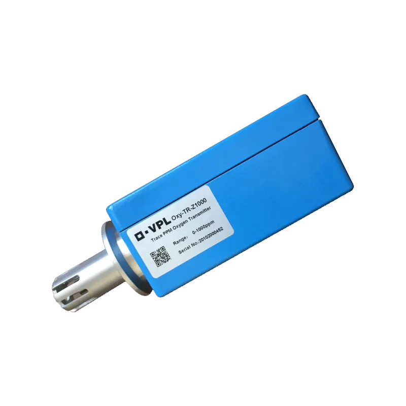
A zirconia oxygen analyzer measures oxygen concentration; it does not remove oxygen. That sounds obvious, but it is the source of a common misunderstanding. When the analyzer shows a slow return to baseline, the purification loop may be working exactly as designed and the analyzer may simply be reporting the true, gradual recovery of a large or regularly disturbed volume. Conversely, a fast analyzer response does not prove that the atmosphere is clean — it proves that the gas reaching the sensor has changed.
A zirconia sensor is an electrochemical cell that operates at elevated temperature and produces a voltage related to the ratio of oxygen partial pressure between the sample and a reference. Practical performance depends on keeping the sensor at its specified temperature, supplying the sample at the right flow, and protecting it from substances that can alter its response. Solvent vapors, particulates, and certain contaminants are typical concerns; where they are present, sample conditioning is part of the measurement design. Calibration also matters, and it should be scheduled rather than treated as a one-time setup.
Two specifications are often confused. Resolution is the smallest change the display can show; accuracy is how close the reading is to the true value. A display with fine resolution may still have wider accuracy, so the digits should not be read as a guarantee. For troubleshooting, the trend and the recovery slope are more informative than any single reading. The glove box zirconia oxygen analyzer page outlines the accessory itself, and its sampling arrangement is worth reviewing whenever a reading seems inconsistent with what the box is doing.
Configuration Choices That Shape Recovery Time
Several configuration choices influence how quickly a purified box returns to baseline, and most of them are decided at the specification stage rather than in the field.
The most direct is the ratio of purification capacity to internal volume. A larger chamber with the same circulation and purification hardware will recover more slowly after the same disturbance. Adding stations increases the number of people who can work, but it does not increase purification capacity; the loop still serves one volume.
The circulation rate determines how often the chamber gas passes through the purification media. Higher flow shortens recovery, within the limits of the column and the pressure balance of the box. Column configuration matters as well: systems with two columns can regenerate one while the other stays online, which avoids the interruption that occurs when a single column must be taken out of service.
The antechamber design sets how much air enters with each transfer and how effectively it is removed before the inner door opens. A smaller antechamber with a well-defined cycle can disturb the main atmosphere less than a large one, even if the small one requires more cycles. Glove material and thickness influence water permeation over long periods. Equipment installed inside the box — hot plates, pumps, printers, and similar devices — adds heat and outgassing that the loop must absorb.
Where the monitoring point sits also affects what the numbers mean. A sensor in the circulation loop sees gas that has just passed through the purification media and may read lower than the bulk chamber atmosphere during a disturbance. A sensor in the working volume reports what the operator experiences, including local pockets. Whichever arrangement is used, the location should be known and kept consistent, because a change in monitoring point can look like a change in box performance.
Single-sided versus double-sided is largely a workflow and footprint decision. A double-sided box allows operators on two faces and can reduce the need to pass samples across the chamber, but it generally increases volume. A single-sided, two-station box keeps one working face, supports one or two operators side by side, and concentrates the atmosphere in a smaller envelope. For a given application, the right question is not which layout is "better" but which one matches the number of users, the sample transfer frequency, and the acceptable recovery time. Exact capacities, flow rates, and performance figures for a specific model must come from the manufacturer's datasheet for that configuration; values from one model should not be assumed to apply to another.
Before You Change Hardware: A Verification Checklist
- Log before you adjust. Record oxygen and moisture for several hours with no activity, then record the recovery curve after a defined event, such as one empty antechamber cycle. Without a baseline, every later change is guesswork.
- Separate transfer load from loop performance. Repeat the test with and without a sample. If the empty transfer recovers normally, the loop is likely healthy and the sample is the load.
- Verify the gas supply. Check the certificate or measurement for purge and regeneration gas, and inspect lines and connections for the possibility of moisture ingress.
- Review the regeneration record. Confirm the last regeneration was completed as intended and that the cycle count is consistent with the way the box is used.
- Inspect the physical enclosure. Gloves, port rings, viewport seals, feedthroughs, and joints. A pressure-hold test is a useful first screen, but it should be interpreted with the box's design pressure in mind.
- Check the analyzer itself. Calibration status, sample flow, filter condition, and whether the sensor is exposed to vapors it is not designed to tolerate.
- Review material handling. Reduce paper and cardboard, use sealed containers, pre-dry materials where the process allows, and confirm that solvents are managed by an appropriate path.
- Only then consider hardware changes. Additional purification capacity, a second column, a modified antechamber cycle, or a different glove material are options — but they should be justified by the trend data, not by a single reading.
When discussing the situation with a supplier, the most useful information is a description of the box configuration, the internal volume, the purification arrangement, the gas used, the typical material load, the transfer routine, the observed recovery time, and the analyzer type and calibration history. That package of information lets the supplier judge whether the recovery time is normal for the configuration or whether something needs attention.
A two-station single-sided purification glove box is one shared atmosphere served by one purification loop. Recovery time reflects the balance between what enters and how fast the loop can remove it, and it should be evaluated with the same care as the baseline value itself. Most slow-recovery cases are resolved by measuring carefully, separating transfer load from loop performance, and confirming the parameters that were assumed at specification — not by replacing components on the first sign of a rising reading. For the configuration described here, the two-station single-sided purification glove box page is the appropriate starting point for confirming volume, purification arrangement and available options.
