
Controlled-atmosphere work rarely fails because a purifier is technically incapable. It fails because the enclosure, the transfer staging, and the daily workflow were specified independently, and the purification loop ends up absorbing a load it was never sized for. A twelve-station, double-sided, split-type glove box with an integrated gas purification system is a useful case study, because at that scale the interactions become impossible to ignore.
The questions worth answering before a purchase order are these: when a high station count actually helps, what a split frame does to installation and leak testing, how a closed loop behaves under overlapping operator activity, why analyzer readings recover slowly after a transfer, and how an accessory such as a KF40 Ethernet feedthrough fits into a data-collection strategy.
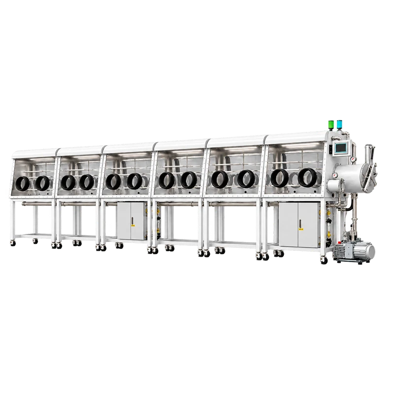
Why a Twelve-Station Layout Changes the Atmosphere Control Problem
A three-port box is a small, relatively quiet system. Twelve stations is a different problem class. Volume grows, internal surface area grows, the total length of elastomer sealing grows, and, most importantly, the number of gloves grows. Every glove is a thin polymer membrane separating a controlled atmosphere from laboratory air, and it is continuously permeable to water vapor and oxygen at a low but non-zero rate. A twelve-station enclosure may carry twelve or more gloves, and permeation load scales with that number. The purification loop therefore has to remove a baseline inflow that never stops, on top of whatever the work introduces.
Throughput adds a second, spikier load. In a busy laboratory, transfers overlap: one operator loads a sample into the antechamber while another opens a small chamber, and a third brings in a solvent-bearing part. Each event injects a small volume of air or a burst of outgassing. With twelve stations these events are no longer separated by long recovery windows, so the loop sees a nearly continuous disturbance rather than isolated spikes. This is why station count is an atmosphere-control decision, not only an ergonomic one.
Equipment inside the box contributes as well. Balances, sealing tools, microscopes, and heaters occupy volume, and anything that runs warm will encourage moisture to leave surfaces it has been adsorbed on. The result is not a dramatic failure mode but a persistent background load that determines how often the purifier columns need regeneration and how long the atmosphere takes to settle after each transfer.
There is also a zoning temptation worth resisting. It is convenient to plan the enclosure so that one end is used for weighing and the other for sealing. Zoning works well as an organizational convention inside one shared atmosphere, and it fails as a substitute for separate environments. If two processes genuinely need different gas compositions, different pressures, or different contamination limits, the answer is two enclosures, not twelve stations in one.
What a Double-Sided Split Frame Actually Changes
Two-sided work and the reach question
A double-sided enclosure places operating faces on both long sides, which changes how work is scheduled rather than merely how much space is available. Shift handover can happen without a full transfer sequence, two processes can run in parallel on opposite faces, and shared instruments can sit in the central band where both sides can reach them. For a materials laboratory running long experiments alongside sample preparation, that parallel capacity is often the real reason to choose this layout.
The constraint is arm reach. Usable working depth is limited by arm length and glove length minus a comfortable extension, and the centerline zone is genuinely shared space where two operators reaching at once will collide. Good layouts therefore put instruments and fixtures along the center band and reserve the outer bands for hands-on manipulation. A twelve-station double-sided split-type glove box with gas purification system is usually planned this way from the start, because it is difficult to reorganize later.
More faces also mean more gloves, more glove ports, more lighting, and more sealing length per unit of usable volume. Combined with the permeation argument above, a double-sided enclosure needs a purification loop with capacity for that baseline load, and it needs supply and return ducting arranged so that gas actually mixes. In a long enclosure, a single supply inlet and a single return can leave sluggish pockets of gas near the ends. Ask how the circulation path is laid out, how many supply and return points exist, and where analyzers sample; do not assume the whole volume behaves identically.
Joints, transport, and on-site assembly
Split-type construction generally means the system ships as separate assemblies, typically with the enclosure and the purification cabinet built and moved as distinct units and joined on site. The benefit is practical: large enclosures often have to pass through a laboratory door, a service lift, or a corridor with a tight turn, and a monolithic box may simply not fit. The cost is that every joint created on site is a potential leak path, and each one must be sealed and verified rather than assumed.
Before ordering, confirm with the manufacturer which interfaces are welded and which are gasketed, who performs the leak test, which method is used, and what acceptance criterion applies. Ask whether the purification cabinet serves one continuous enclosure or several sections through isolation valves, and if isolation is used, how a section can be taken offline without disturbing the rest. These are configuration questions with long-term consequences, not installation details.
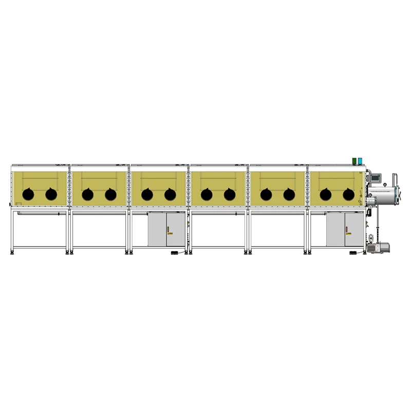
Inside the Purification Loop
What closed-loop circulation does, and what it does not do
In a continuously purifying glove box, gas is drawn from the enclosure, pushed by a blower through one or more purifier columns, and returned. The columns combine an oxygen-removing medium, typically a copper-based catalyst, with a moisture adsorbent, typically a molecular sieve. Circulation runs continuously, so the loop works constantly against leaks, permeation, and outgassing. Analyzers monitor the result; they do not create it.
Three limits matter in practice. First, the loop treats gas that reaches it, so regions with poor circulation recover more slowly than regions near the return duct. Second, the loop removes water and oxygen, and it does not remove organic solvent vapor or trap particles. Those tasks belong to separate media, such as a solvent adsorbent for organic vapor and a HEPA filter for particles, and neither substitutes for water and oxygen removal. Third, the purge cycles used during transfer only dilute residual air; they do not eliminate it, and they consume inert gas.
Regeneration: the scheduled interruption
Purifier media have finite capacity. Over time the oxygen catalyst is consumed chemically and the sieve fills with adsorbed water, so the columns must be regenerated. In general terms this means heating the medium, exposing the oxygen catalyst to a reducing gas mixture, and driving moisture out of the sieve. The specific gas composition, temperature profile, and duration are defined by the manufacturer for that model and belong in the operating manual. They are not parameters to improvise, and they should not be copied from a different system.
Operationally, the important point is that regeneration takes the column out of normal service for a period measured in hours rather than minutes. Plan it around work cycles, and confirm whether the enclosure can continue operating at reduced performance during regeneration or whether the atmosphere must be protected by other means. Regeneration frequency is not a fixed specification either. It depends on leak rate, glove permeation, sample load, solvent use, and how often the box is opened.
If the columns need regeneration more often than the workload allows, adding capacity is usually more effective than shortening the regeneration interval past the manufacturer's recommendation. A larger column, a second purification cabinet, or fewer gloves per unit of internal volume all reduce the load the media must carry. Do not confuse this with the practice of purging: replacing the atmosphere with fresh inert gas dilutes contamination, while circulation through regenerated media removes it.
Transfer Events and Slow Analyzer Recovery
Antechamber cycles and what they actually remove
A vacuum antechamber is a small chamber with its own door to the laboratory and its own door to the box atmosphere, connected to a vacuum pump. The sequence is familiar: load, seal, evacuate, refill with inert gas, repeat, then open into the enclosure. Each evacuation and refill dilutes the residual air inside the chamber. The residual falls roughly geometrically with the number of cycles, so the first two cycles do most of the work and later cycles give diminishing returns, but the absolute residual also depends on how low the chamber pressure actually goes. That chamber pressure is not the same quantity as the pump's ultimate vacuum.
Practical choices follow from this. Porous carriers, filter paper, high-surface-area powders, and anything exposed to humid air hold adsorbed water and release it into the box after transfer, so extra cycles help. Solvent-wet parts introduce organic vapor that the water and oxygen media will not handle. The small chamber door seal is itself a wear item and should be inspected periodically, because a hardened or damaged seal admits air directly into the enclosure.
Reading a slow recovery as a symptom
When moisture or oxygen readings take unusually long to return after a transfer, it is tempting to conclude that the purifier has failed. That conclusion is usually premature. The reading reflects the size of the disturbance, the loop's ability to mix and treat it, and where the analyzer samples. Categories worth checking, in order:
- Disturbance size and nature. How much air entered, and whether the transferred items outgas. Large, porous, or solvent-bearing loads take longer to clear.
- Circulation and mixing. Where the analyzer samples relative to supply and return, and whether parts of a long enclosure are poorly swept.
- Ingress paths. Gloves, glove port seals, door seals, feedthrough seals, and assembly joints. A pressure decay test addresses these; a rising moisture trend with stable pressure points elsewhere in the system.
- Media condition. Columns near the end of their working capacity recover more slowly and need regeneration sooner.
- Instrument behavior. Sampling lag, calibration age, and sensor drift can look like a slow system even when the atmosphere is fine.
The diagnostic value comes from separating these possibilities. If the enclosure holds pressure but water content climbs steadily, look at outgassing and permeation. If pressure decays while the box is idle, look for a leak. If readings are slow only after large transfers and otherwise normal, the loop may simply be undersized for the workload. None of this can be settled without measurement, which is why a documented leak test and a calibrated analyzer matter more than an optimistic figure on a datasheet.
Units, Resolution, and What a Number Really Means
Numbers from different parts of a glove box specification are frequently compared as though they described the same quantity. They do not. Box working pressure is a pressure, in pascals or millibars, describing how the enclosure is operated, often slightly positive or slightly negative relative to ambient. Antechamber vacuum is a chamber pressure achieved during a transfer cycle. Pump ultimate vacuum is a property of the pump alone, measured under defined conditions with no chamber load. Leak rate is a rate of pressure change or a gas flow through a leak. Water content expressed in ppm, or as a dew point, and oxygen content expressed in ppm, are concentrations in the gas. None of these substitutes for another.
Water content is a good example of how easily units mislead. A dew point and a ppm figure describe the same physical quantity in different scales, and converting between them requires a stated pressure and a defined sampling condition. Quoting one while testing the other is a common source of confusion in specification discussions.
Two further distinctions are worth insisting on. A reachable value, meaning the best figure a system can show after a long purge with no work in progress, is not the same as a value the supplier will guarantee continuously under a defined load, so ask which figure is which. And resolution is not accuracy: a display that reads to 0.1 ppm is not thereby accurate to 0.1 ppm. Accuracy depends on calibration, measurement span, and sensor principle, and it degrades over the calibration interval. If a specification cannot be tied to a stated condition, treat it as a topic to clarify rather than a fact to design around.
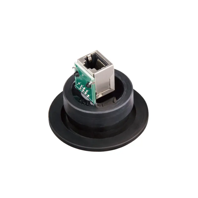
Bringing Network Data Through the Wall: KF40 Ethernet Feedthrough
Instruments and data systems raise a specific integration question: how do you get a network connection from inside the enclosure to the laboratory network without adding an opening? The answer is a feedthrough, a sealed connector mounted to a port in the enclosure wall. A KF40 Ethernet feedthrough is one such part, using a KF (ISO-KF) 40 flange format to carry an Ethernet link through the wall.
Typical uses are straightforward. An analytical balance, a logging sensor node, an in-box camera, or a potentiostat with a network interface can remain inside the controlled atmosphere while its data goes to a computer outside. Analyzer readings can be logged continuously rather than transcribed by hand. Remote support becomes possible without an operator standing at the box, and because the connection passes through a flange rather than a door, the enclosure is not opened to run a cable.
Selection depends on details that should be confirmed rather than assumed. Is a spare KF40 port available on the enclosure, and is it accessible without obstructing glove movement? Is the feedthrough rated for the pressure regime and leak-tightness the application requires? Are the seal and cable jacket materials compatible with the atmosphere, remembering that solvent vapor ages polymers and a swollen seal becomes a leak path? Is there sufficient internal clearance and strain relief for the cable, and is the outside end routed to a switch or workstation? For applications that stream video or high-rate data, confirm the link supports the required bandwidth. If the payload is not Ethernet at all, whether analog signals, thermocouples, fluid lines, or optical fiber, the correct choice is a feedthrough designed for that payload rather than an adapted network part. Accessories only help when the enclosure and the accessory are genuinely compatible, so confirm the pairing with the supplier of the box.
Configuration Checklist Before You Order
The purpose of a specification conversation is to convert an intended workflow into parameters the supplier can design against. The items below cover most of the decisions that become expensive to change later.
| Parameter | Why it matters | What to ask |
|---|---|---|
| Working pressure range | Defines how the enclosure is operated and how the doors and seals behave | Verify units, normal operating point, and permitted deviation |
| Antechamber vacuum | Determines how much residual air each transfer cycle leaves behind | Ask for the chamber pressure reached, not the pump's ultimate vacuum |
| Leak rate and test method | The dominant long-term load on the purification loop | Ask for the method, acceptance criterion, and whether it is repeated on site after assembly |
| Water and oxygen figures | Reachable values and continuous guarantees are different commitments | Ask which figure is guaranteed, under what load, and for how long |
| Circulation layout | Long enclosures can develop regions with slow mixing | Ask about supply and return placement and analyzer sampling location |
| Regeneration procedure | Media must be restored periodically, taking the column offline | Ask for the model-specific procedure, gas supply requirements, and expected interval under your workload |
| Glove and seal materials | Permeation and chemical compatibility both depend on the selection | Match the material to the samples and solvents you will actually handle |
| Feedthrough and port plan | Data, power, and fluids must cross the wall without opening the box | List payloads, then confirm flange format, port availability, and spacing |
Alongside the table, prepare a short description of the work itself: which materials will be handled, whether they are porous or solvent-bearing, how many operators will work simultaneously and on which sides, which instruments must live inside the box, whether data must leave the enclosure continuously, and what the worst-case transfer looks like. That description drives loop capacity, port count, and the accessory list far more reliably than a target ppm figure, and it gives the supplier something concrete to design against.
Finally, treat commissioning as a phase with acceptance criteria rather than a formality: a documented leak test with a stated method and limit, analyzer calibration, a circulation check, and the manufacturer's regeneration procedure for the specific model. Review the twelve-station purification glove box configuration against those criteria before the work begins. A twelve-station, double-sided, split-type glove box with a gas purification system can support a very productive laboratory, but it will only do so when the atmosphere control is designed around the way people actually work in it.
