
Why a Six-Glove, Double-Sided Purification Box Changes the Atmosphere Problem
A glove box with a gas purification system is usually introduced through its headline elements: a sealed enclosure, a closed circulation loop, purification columns, and sensors that report oxygen and moisture. Those elements describe the architecture, not the size. When the enclosure is built as a six-glove, double-sided workstation, one circulation loop must serve a larger internal volume, two working faces, and several operators who may be running different processes in the same shift. The practical question stops being whether the box purifies and becomes how quickly the atmosphere returns to its working baseline after a disturbance, and which component sets that recovery time.
Two things scale with enclosure size. The first is gas volume: a larger box holds more working gas, so a fixed amount of leaked or desorbed contamination dilutes into a larger quantity of gas, but that contamination also takes longer to be swept back through the purification loop. The second is the number of interfaces. Every glove port, antechamber door, viewing window gasket, feedthrough and instrument connection is a possible path for water and oxygen to enter. A double-sided design doubles the number of working faces and therefore the number of glove ports, doors and operator interactions that can disturb the atmosphere simultaneously.
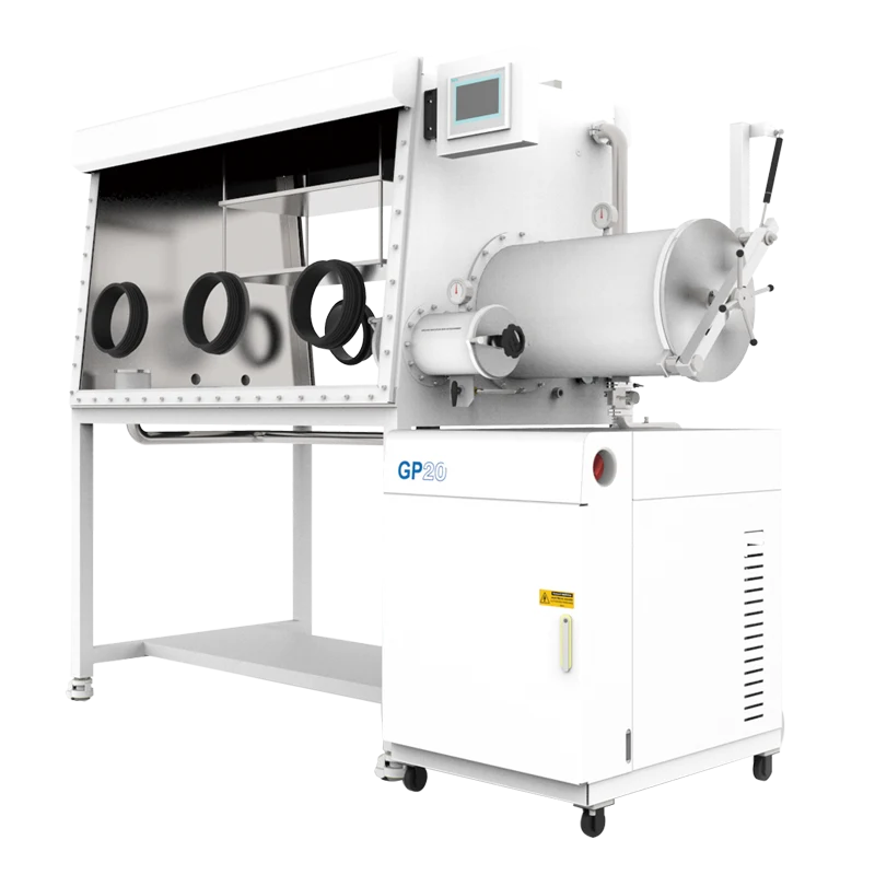
Systems such as the Six-Glove Double-Sided Glove Box with Gas Purification System are therefore better evaluated as a shared environment than as a personal workstation. If two operators open an antechamber at the same moment as a third changes a glove, the loop sees a step change in load rather than a smooth, predictable leak. Understanding recovery means understanding how that load is generated, how it is removed, and where the measurement is actually taken.
What “Recovery” Actually Measures
Recovery time is not a single property of a box. It is the outcome of at least three distinct processes that are often discussed as if they were the same thing: inert gas replacement, continuous closed-loop purification, and regeneration of the purification media. Confusing them leads to wrong expectations and, frequently, to wrong troubleshooting.
Replacement, circulation and regeneration are different operations
Inert gas replacement, sometimes called purging, reduces oxygen and moisture by diluting the existing atmosphere with dry inert gas and venting the mixture. It is a batch process. Each exchange brings the concentration down by a fraction, so repeated cycles are needed to approach a low level, and the working gas is consumed in the process.
Closed-loop circulation is continuous. Gas is drawn from the enclosure, passed through purification columns that chemically or physically bind oxygen and water, and returned to the box. As long as the loop runs and the media are active, the atmosphere is being cleaned rather than merely diluted. Because the loop is closed, the working gas is largely conserved.
Regeneration is what restores the media once they are saturated. It normally requires isolating the columns from the enclosure, heating them, and passing a regeneration gas mixture specified by the equipment manufacturer. During regeneration, the box is typically on purge or standby rather than being actively purified. A recovery curve measured during regeneration will look nothing like one measured during normal circulation, and it is worth knowing which mode the system is in before drawing conclusions.
Where the reading comes from matters as much as the reading
Oxygen and moisture analyzers sample the gas at a specific point, usually on the return line from the loop or at a sensor port on the box wall. They do not measure the atmosphere in every corner. In a long, double-sided enclosure, gas movement near the far glove ports can differ from conditions at the sensor, especially when the loop flow is high but poorly distributed or when fixtures and shielding obstruct the internal path.
Sensor characteristics also shape what you see. Response time, resolution and calibration drift are separate properties. A sensor can display a low value while the average concentration elsewhere is higher, or it can take minutes to register a change that happened quickly. Resolution is the smallest change a device can display; it is not the same as accuracy, and it does not by itself prove that the atmosphere is at that level. When a reading and a process result disagree, the measurement chain — sampling point, sensor condition, calibration gas, and last calibration date — deserves the same scrutiny as the purification loop.
The Transfer Path Is Where Atmosphere Quality Is Usually Lost
Most recovery complaints begin with a transfer. A sample enters, a tool leaves, a substrate is loaded, an electrical measurement is made. Each of these events breaches the enclosure boundary in a controlled way, and the quality of that control determines how large the disturbance is.
Antechamber volume, cycle discipline and vacuum quality
An antechamber is a small airlock. Its job is to remove the bulk of the air carried in with an object before that object enters the main enclosure. The relevant questions are how large the chamber is relative to the items being passed, how deep a vacuum it can reach, how many purge and evacuation cycles are performed, and how the door seals behave over time.
A chamber that is barely large enough for the sample may seem efficient, but a tight fit can trap air in crevices and behind fixtures. Conversely, a large chamber used for small items wastes working gas and lengthens each cycle. The number of cycles matters more than most people expect: a single evacuation and refill leaves a meaningful fraction of the original air behind, and repeating the cycle is what drives the residual down. Pressure rise after isolation — watching how quickly the chamber pressure climbs when the pump is valved off — is a simple and useful indicator of leakage or outgassing in the chamber itself.
Objects also carry contamination on their surfaces. Solvent films, adsorbed water on porous ceramics, and residues on machined parts all release vapor once inside. Pre-drying or pre-vacuuming samples outside the box is often the single most effective way to protect recovery time, and it costs nothing but a little schedule discipline.
Gloves, ports and the slow leak you cannot see
Gloves are the most frequently replaced part of a box and one of the most important for atmosphere quality. Elastomer gloves are not perfectly impermeable: water vapor and oxygen permeate through the material at a low but continuous rate, and that rate depends on the polymer, the glove thickness, the exposed surface area, and the local humidity and temperature in the room. A box with six glove ports has more permeation area than a small enclosure, and the loss is proportional to how long the gloves are mounted, not to how often they are used.
Mechanical damage is more abrupt. Pinholes, cuts near the cuff, and seals that have taken a compression set will produce a leak that may be small enough to escape a casual inspection. The practical checks are a visual inspection at each glove change, a pressure decay test of the whole enclosure, and attention to the glove port O-rings and clamping surfaces, which should be clean, correctly seated, and free of trapped particles or solvent residue.
Feedthroughs: necessary penetrations, necessary care
Electrical measurement is one of the main reasons to bring a signal through the wall rather than a whole instrument. A feedthrough lets a conductor, thermocouple or test lead cross the enclosure boundary without opening a door, so the atmosphere is disturbed once — at the sealed interface — instead of repeatedly, at a large opening.
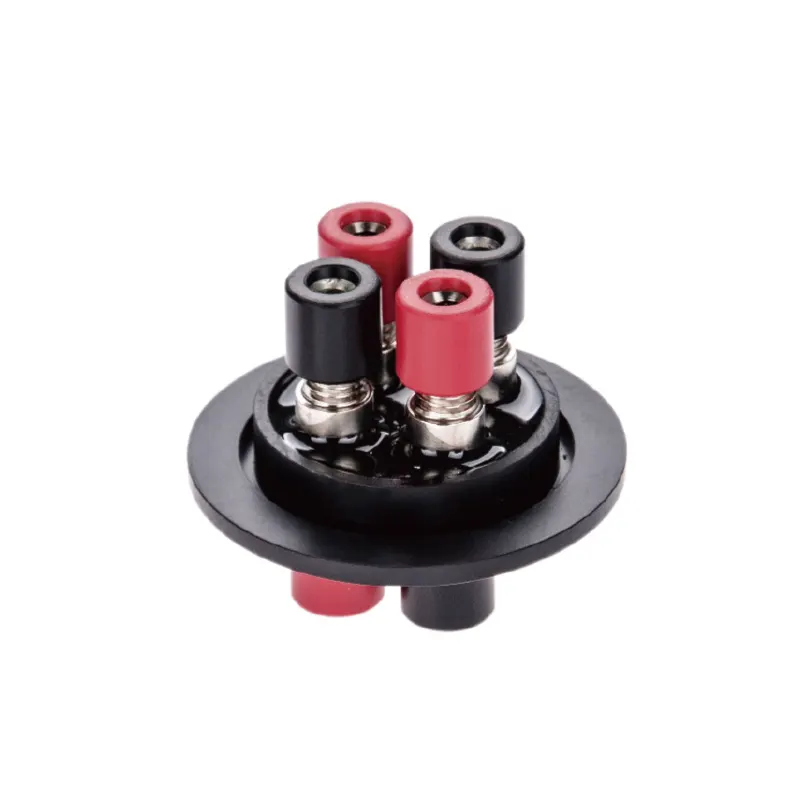
The KF40 Electrical Test Lead Feedthrough is an example of this class of accessory: a KF-flanged fitting that carries electrical test leads through a vacuum-compatible interface. Its behavior in a system depends on details that are easy to overlook. The O-ring must be compatible with the gases and any solvent vapor present. The flange clamp must be correctly oriented and tightened so the seal is compressed evenly. The cable jacket and insulation inside the box must be low-outgassing; a length of ordinary wire with plastic insulation can release more water vapor than the feedthrough leaks. Cable routing matters too, since a lead that crosses the working area can be snagged by a glove and pulled loose.
It is worth checking with the manufacturer whether a KF40 port is available or can be provided on the specific enclosure in question, and where it should be positioned relative to the working faces and the return-gas path. Not every box has a spare flange, and not every accessory is compatible with every enclosure. Adding a penetration is a design decision, not a universal upgrade: each added interface must be leak-tested and maintained like the rest of the boundary.
How the Purification Loop, Columns and Working Gas Shape Recovery
Once contamination is inside, removal depends on the loop. A typical purification system circulates gas through one or more columns containing media that remove water and oxygen by different mechanisms. Moisture is usually taken up by an adsorbent such as molecular sieve, which captures water molecules in its pore structure. Oxygen is typically removed by a reactive medium, often a copper-based catalyst, that binds oxygen chemically. Because the two mechanisms are different, the two media saturate at different rates and are regenerated under different conditions.
This is a useful diagnostic distinction. If moisture recovers slowly while oxygen recovers normally, the water-removal pathway is the place to look: a saturated or partially regenerated sieve bed, an unusually wet load, a humid room, or a glove permeation problem. If oxygen lags while moisture behaves, the oxygen-removal medium, the loop flow, or an air ingress path is the more likely suspect. If both rise together and stay elevated, a boundary breach or an unusually large transfer is more plausible than a media problem.
Working gas choice interacts with all of this. Nitrogen and argon have different densities and heat-transfer properties, and both behave differently from the gas mixture used during regeneration. Circulation flow rate, pressure setpoint and the box pressure control scheme also affect how quickly a localized contamination pocket mixes into the main flow. A box that holds pressure well but moves gas slowly will show a long, gentle recovery curve; one with strong circulation may recover faster but can also stir up particles and disturb delicate samples.
Particle filtration and solvent management belong to a separate discussion. A HEPA filter removes particles; it does not remove water or oxygen. Solvent adsorbers reduce organic vapor levels and protect both samples and purification media, but they are not a substitute for water and oxygen purification. Treating these functions as interchangeable leads to systems that look well equipped but recover poorly after a solvent-heavy process.
Symptoms, Probable Causes and First Checks
The table below maps common observations to plausible mechanisms. It is a diagnostic starting point, not a fault diagnosis for a specific machine; the order of checks should follow the system documentation and the manufacturer's guidance.
| Observation | Plausible mechanism | First checks |
|---|---|---|
| Both oxygen and moisture jump after every transfer | Transfer practice admits more air than the loop can remove quickly | Antechamber cycle count and vacuum depth; load size and porosity; door seal condition |
| Moisture recovers much more slowly than oxygen | Water load exceeds sieve capacity or sieve regeneration was incomplete | Recent regeneration record; wet or porous loads; glove permeation; room humidity |
| Readings drift upward overnight with the box idle | Continuous ingress through a seal, glove or fitting | Pressure decay test; glove inspection; flange and O-ring condition; sensor drift |
| Readings recover near the sensor but not at the far face | Poor internal mixing or obstructed circulation path | Fixture placement; return path; circulation flow setting |
| Recovery worsens after a new feedthrough is added | Sealing, tightening or outgassing at the new interface | Flange clamp orientation and torque; O-ring material; cable insulation inside the box |
| Sensor shows a low value while process results degrade | Sampling point, calibration or sensor condition rather than the loop | Calibration date and gas; sampling location; cross-check with a second method |
Matching Configuration to Workflow: Ports, Faces and Split Designs
Recovery performance is set long before the box is installed, at the point where the configuration is chosen. The number of glove ports and the decision to use one working face or two determine how many people can work at once, and therefore how many simultaneous disturbances the loop has to absorb.
A double-sided box allows two operators to face each other, which is useful when a process requires one person to load and another to observe or measure, or when a long workflow benefits from two stations that share an atmosphere. The trade-off is a larger boundary, more glove ports, and a greater chance that one operator's transfer affects another's sample. For a six-glove layout, the practical questions are whether the ports are organized so that each pair has clear access to the antechamber and the return path, and whether the internal volume supports the fixtures, heaters, or test equipment that will actually be installed.
Split or separate configurations, where the purification unit sits apart from the enclosure and connects by ducting, change both service access and the footprint. Servicing columns becomes easier without opening the box, and the enclosure itself can be positioned for ergonomics. The cost is additional ducting and connections, each of which must be leak-tight and correctly sized for the loop flow.
Because recovery depends on volume, circulation and interface count together, the same purification hardware can feel fast on a compact box and slow on a large one. That is not a defect; it is a design consequence that should be anticipated when the workstation is specified.
What to Confirm Before Specification and Verification
Most of the information a supplier needs is about the work, not about the hardware. A short written summary of the application will usually produce a more appropriate configuration than a comparison of catalog numbers.
Application information worth preparing
- Materials and samples: composition, sensitivity to oxygen and moisture, typical mass and surface area, and whether they are porous, powdered or solvent-bearing.
- Processes inside the box: heating, coating, welding, electrical testing, weighing, or storage, and the temperature and vapor loads each one creates.
- Operator count and shift pattern: how many people work at the same time, and from which face.
- Transfer frequency and typical load size, since antechamber volume and cycle count should match the real workload.
- Instrumentation and connections: sensors, probes, power requirements and signal types that must cross the boundary.
- Solvent and particle generation, so that adsorbers and filtration are sized for the actual process rather than added later.
- Site conditions: ambient humidity, room temperature, available height and floor space, and how the box will be moved into position.
- Target atmosphere and acceptable recovery time, expressed in your own units and measurement method.
Verification and routine practice
After installation, a few habits make recovery behavior predictable. Record a baseline: with the box empty and clean, note the oxygen and moisture readings, the pressure decay rate over a defined interval, and the time needed to recover after a standard transfer. Logging that baseline makes later changes meaningful, because a slow drift is easier to interpret than an abrupt one.
Establish a standard antechamber procedure and follow it consistently, including how many cycles are used and how long the chamber is held under vacuum. Inspect gloves on a schedule and after any incident. Check flange and O-ring condition at every service interval, including on accessories such as electrical feedthroughs, and verify sensor calibration with a certified reference gas at intervals appropriate to the process requirement. Keep a simple log of regenerations, media changes and unusual transfers so that a future recovery problem can be compared against a known history rather than guessed at.
Finally, be cautious about any claim that a box eliminates oxygen, moisture or contamination entirely, or that it requires no maintenance. A purification system holds a low working level and returns to it after disturbance; the achievable level and the recovery time depend on the enclosure, the load, the loop, the media state and the measurement method. Ask what conditions a quoted figure applies to, and whether it is a capability of a specific configuration or a guarantee for continuous operation. Getting that distinction clear before purchase is what keeps a six-glove, double-sided purification box working as a shared, stable environment rather than a source of unexplained process variability.
