
The oxygen reading on an acrylic glove box can be misleading. After a purge starts, the number may fall quickly and then stall, or it may recover only after a long delay following a sample transfer. A high plateau, a slow tail, and an unstable reading can all look like the same “slow recovery” problem, yet they point to different parts of the system. The useful question is not simply why the analyzer is slow. It is which part of the chain—from gas supply and enclosure sealing to sample transfer and measurement—is limiting the change.
This discussion is written around the GBT Series Acrylic Glove Box and the glove box trace oxygen analyzer used with it. It separates atmosphere behavior from instrument behavior, explains why an acrylic enclosure needs a different diagnostic approach from a continuously purified glove box, and lists the details worth confirming before a configuration is fixed.
Slow Recovery Is a System-Level Signal
“Slow recovery” usually refers to one of two events. The first is the initial purge-down of a box that has been open to air. The second is the return to a working atmosphere after a transfer, a glove change, or a brief opening. They are related, but they are not the same test. An initial purge has to remove the bulk air in the chamber and the air held in tubing, filters, and transfer volumes. A recovery test starts from a much lower oxygen level and is therefore more sensitive to small leaks, surface release, and analyzer lag.
An oxygen analyzer reports concentration at its sample point. It does not remove oxygen, and it cannot make a leaking box behave like a sealed one. If the reading falls slowly while the purge is running, the cause may be dilution limited by purge-path design, air entering through a seal or glove, oxygen desorbing from surfaces, or sample gas that is not reaching the sensor promptly. If the reading is slow only when a sample is introduced, the transfer method and the material load deserve attention first.
Without a record, these cases blur together. A useful log includes the starting reading, the time the box was opened, the purge gas and flow, the outlet or sample-point reading, the analyzer’s stabilization time, and the materials placed inside. Without those observations, “the box is slow” is not a diagnosis. It is a description of a result that still needs to be assigned to a cause.
What the GBT Acrylic Enclosure Can and Cannot Do
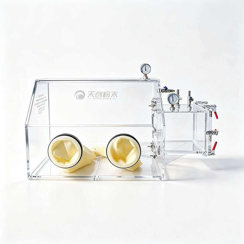
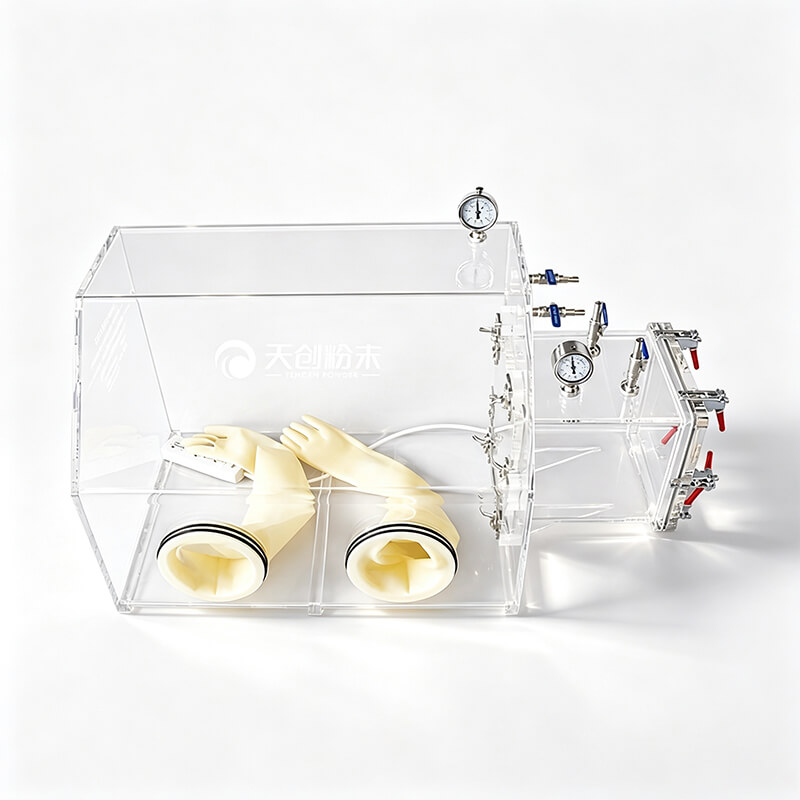
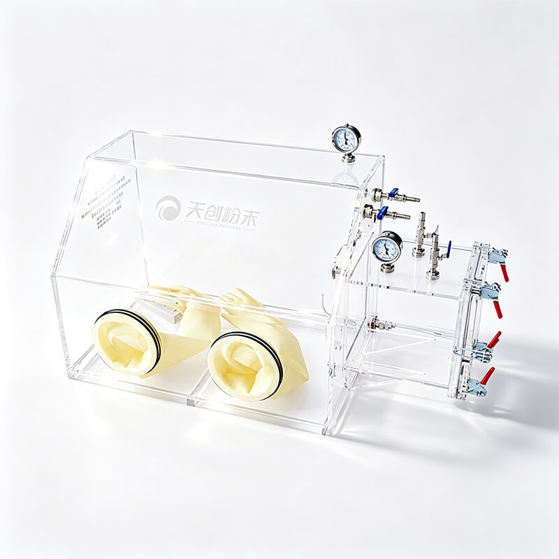
The GBT Series is an acrylic glove box platform. Its transparent working chamber makes it useful for operations where the sample must be seen and manipulated directly, and for research setups where an economical isolated atmosphere is more appropriate than a large stainless-steel installation. The family is not a single specification. Isolation, micro-vacuum, and vacuum versions differ by model and wall thickness, and not every version can be evacuated, fitted with an antechamber, or connected to a purification system. Those are configuration facts to verify, not assumptions to carry from one acrylic box to another.
This distinction matters when oxygen recovery is being judged. A simple acrylic isolation box may be designed for purging with inert gas and for protecting a sample from room air during handling. It should not automatically be expected to reach, hold, or recover to the same oxygen level as a closed-loop glove box with a regenerative purifier. If the application needs a continuous low-oxygen atmosphere, the first question is whether the chosen GBT configuration includes the necessary purification and monitoring hardware—not how long the purge should be run.
Acrylic also imposes practical limits that affect diagnostics. The enclosure is chosen for visibility and access, but its pressure capability, solvent compatibility, and cleaning requirements must be checked against the actual model. Some solvents, adhesives, and cleaning agents can affect acrylic, and a pressure differential that is harmless in a metal box may be inappropriate here. Do not apply house vacuum or a high purge pressure to an acrylic box unless the manufacturer’s procedure permits it. A cautious operating envelope is part of the experiment, not an obstacle to it.
Where the Oxygen Comes From
When recovery is slower than expected, it helps to separate sources of oxygen and oxygen-containing air. The box is not a perfect barrier, the load is not always clean, and the plumbing is part of the atmosphere system. Four areas account for many disappointing results.
Seals, gloves, and small leaks
Air can enter through glove cuffs, glove-port O-rings, door gaskets, valve stems, tubing connections, and feedthrough seals. A glove that looks intact can still have a pinhole, a porous area, or a poor seal at the cuff. A door gasket can look clean and still fail to seat because of a trapped particle, a hardened edge, or uneven compression. Small leaks are often more visible during recovery than during a fast initial purge, because the purge flow is diluting the incoming air while the recovery test is trying to hold a low level.
Leak checking should follow the manufacturer’s method for the specific box. Pressurizing an acrylic enclosure without approval is not a neutral test; it can stress panels and joints. Soap solution, pressure-decay checks, and tracer-gas methods each have limits, and the acceptable method depends on the hardware. The practical point is that a slow oxygen rise at rest, with no transfer and no purge, is a strong reason to examine the boundary before blaming the analyzer.
Transfers, antechambers, and trapped volume
Every object brought into a glove box carries air on its surfaces and inside its packaging. A bottle with a loose cap, a porous sample, a folded bag, or a container with a narrow neck can hold air that is released after the outer door is closed. If the box has an antechamber, its volume and purge method matter: a small chamber that is only briefly purged can pass a concentrated plug of air into the main chamber. If the box has no antechamber, the transfer procedure itself becomes the dominant air source.
Recovery after a transfer is therefore not a clean test of the box. It is a test of the transfer protocol as well. Unpacking outside the box, wiping surfaces, using a pre-purged bag, or allowing a transfer chamber to cycle according to the manufacturer’s instructions can change the result more than a small increase in main-chamber purge flow.
Outgassing from surfaces and samples
Oxygen and moisture can be held on surfaces and released slowly. Acrylic panels, gloves, gaskets, tubing, and sample containers all have surface layers that can retain air or moisture. Powders, porous materials, solvents, and freshly prepared samples may release volatiles or trapped gas after they are placed inside. A purge that removes the bulk gas phase does not necessarily remove species that are weakly bound to surfaces or diffusing out of a solid.
The result can be a long, flattening recovery curve that is not explained by a single leak. This is one reason a box with no purification may stabilize at a higher oxygen level than the operator expected: dilution is competing with a continuous, low-level release. The right response is to reduce the load, condition or pre-purge materials where the procedure allows, and allow enough time for the atmosphere to mix before judging the final value.
Short-circuiting and poor mixing
A purge inlet and outlet can be close together in a way that lets fresh gas travel directly to the outlet while corners, glove ports, and the far end of the chamber remain poorly swept. The analyzer may then report a local improvement that does not represent the whole box. Mixing is also affected by the physical layout: shelves, transfer boxes, and large samples create dead zones. Recovery can look slow because the sensor is sitting in a pocket that exchanges poorly with the rest of the chamber.
Use the purge points and mixing method specified for the model. Do not add holes or relocate fittings without approval. Where a circulation fan or an internal mixing path is part of the configuration, confirm that it is running and that its flow path is not blocked. Where no forced mixing exists, the placement of the sample point and the wait time before taking a reading become part of the measurement method.
Purge, Vacuum, and Circulation Are Not the Same Tool
Three exchange methods are often discussed as if they were interchangeable. They are not. Purge dilution uses a flow of inert gas to reduce the concentration of air in the chamber. Vacuum-assisted exchange removes air by reducing pressure and then refilling with inert gas, but it is only valid on a box rated for that procedure and only within its permitted pressure range. Closed-loop circulation sends gas through a purifier that removes oxygen and moisture and returns it to the box; it depends on a compatible purifier, blower, and control sequence, and it is not implied by the presence of an acrylic chamber.
Each method has a different failure mode. A purge can be limited by short-circuiting, insufficient flow, or a leak that is larger than the dilution capacity. A vacuum exchange can be limited by the achievable vacuum, the number of cycles, or the amount of air trapped in the load. A purification loop can be limited by a saturated column, a bypass, a low circulation rate, or a leak that adds oxygen faster than the purifier can remove it. Adding more purge gas will not fix a saturated purifier, and replacing a purifier column will not fix a leaking glove.
Regeneration is a separate step from purification. A regenerable purifier has to be taken through its regeneration sequence before it returns to service, and that sequence is defined by the equipment supplier. It should not be confused with routine purging, and it should not be improvised on an acrylic box that was not designed for the temperatures, gas flows, or pressure changes involved. If the GBT configuration does not include a purification system, the operating plan should be written around isolation and purge exchange rather than around a purifier that is not there.
Reading the Trace Oxygen Analyzer Correctly
A glove box trace oxygen analyzer is a measuring instrument, not an atmosphere-control device. It tells the operator what oxygen concentration is present at the sampling point. The displayed number is influenced by the sensor, the sample line, the gas flow, the pressure, the temperature, the calibration, and the time allowed for a response. Before a slow reading is treated as proof of a box problem, the measurement chain should be checked.
Selection starts with the measurement job, not with a single resolution figure. A useful specification discussion covers the required range, the resolution needed to see changes of interest, the accuracy required for a decision, the calibration gases and interval, the response time, the sample flow and pressure limits, and the materials that will contact the sample gas. Resolution is not accuracy. A display that resolves a small change can still be inaccurate if it is not calibrated or if the sample system is biased.
| Specification | What it tells you | What it does not tell you |
|---|---|---|
| Range | The concentrations the instrument is designed to display | Whether the sensor is suitable for the process gas or the expected contaminants |
| Resolution | The smallest displayed increment | The closeness of the reading to the true value |
| Accuracy | The expected measurement error under stated conditions | Performance after an unapproved gas exposure or overdue calibration |
| Response time | How quickly the instrument follows a change at its inlet | How quickly the whole glove box atmosphere changes |
Placement is part of the measurement. A sample point near a purge inlet may read lower than a point near a glove port or a dead corner. A long sample line adds transport delay and can smooth out changes, making recovery look slower than it is. Filters, pumps, and valves in the sample path can adsorb or release oxygen and moisture, and a line that is not leak-tight can dilute the sample with room air. The analyzer should be installed where the sample is representative of the working zone, with a sample path that is short, clean, and compatible with the gas.
Calibration is the other half of confidence. Zero and span checks should use the gases and procedure specified for the analyzer, and the results should be recorded. A calibration gas is not a purge gas, and a zero reading obtained with an empty sample line is not proof that the box is at low oxygen. If the analyzer has alarms or analog output, verify that the alarm setpoint and signal scaling match the actual instrument range. A mis-scaled output can make a normal recovery look like a failure—or hide one.
Finally, distinguish a local reading from a mixed atmosphere. A small acrylic box may have slow internal mixing after a transfer, especially if the load blocks the path between the sample point and the rest of the chamber. The instrument can respond quickly while the gas at its inlet remains a local pocket. In that case the correct fix is a better mixing or sampling method, not a different sensor.
A Diagnostic Sequence That Avoids False Conclusions
A slow recovery is easier to resolve when the checks move from the measurement outward rather than from a guess inward. The following order keeps one variable under control at a time.
- Confirm the analyzer is trustworthy. Check calibration status, sample flow, line leaks, filter condition, and the response to a known gas. Confirm that the displayed units and range match the record.
- Look for a boundary leak. Inspect gloves, cuffs, door gaskets, valve stems, feedthroughs, and tubing. Use only the leak-check method approved for the acrylic enclosure.
- Audit the transfer. Review how the sample was packaged, how long the antechamber or door was open, and whether porous or hollow items were pre-purged. Repeat a recovery test with an empty transfer to separate the box from the load.
- Check purge-path effectiveness. Confirm the inlet and outlet arrangement, the flow actually delivered, and whether the sample point sits in a swept zone. A rotameter setting is not proof of flow at the far end of a long line.
- Review the material load. Solvents, powders, moist surfaces, and fresh materials can release gas after the door is closed. Reduce the load or allow a longer stabilization period before judging the atmosphere.
- Confirm the purification state, if fitted. Check that the purifier is in service rather than bypassed or exhausted, and that regeneration is complete before the box is returned to work.
Repeat tests with the same starting condition and the same transfer time. If the result changes when the analyzer is moved but not when the box is left undisturbed, the measurement path is implicated. If the oxygen rises at rest with the purge off, the boundary is implicated. If recovery improves only when the load is removed, the load or transfer is implicated. These are not proof of a specific defect, but they are useful evidence for a conversation with the equipment supplier.
Configuration Details to Settle Before Purchase
The most expensive slow recovery is the one designed into an unsuitable configuration. Before selecting a GBT acrylic glove box, define the atmosphere target and the way success will be measured. State whether the box must hold a low oxygen level continuously, recover after each transfer, or simply provide short-term isolation during handling. Those are different requirements, and they lead to different choices in chamber construction, transfer hardware, and monitoring.
Provide the supplier with the sample types, solvents, particle size, moisture sensitivity, transfer frequency, and any vacuum requirement. Ask which GBT model and wall thickness are appropriate, whether an antechamber is included and how it is purged, what purge points are available, and whether the chosen configuration can be connected to a purification system. Confirm the pressure limits and the approved leak-test method in writing. If an analyzer is to be fitted, agree on the sample-point location, the sample-line route, the calibration gases, the alarm outputs, and who will verify the installation.
A practical specification package includes:
- the required oxygen level and the time allowed to reach it;
- the largest and most outgassing load expected at one time;
- the transfer method and the acceptable air ingress per transfer;
- the purge gas, supply pressure, and available exhaust route;
- the solvent and cleaning agents that will contact the acrylic;
- the monitoring range, accuracy, calibration interval, and data record;
- the acceptance test: what will be measured, where, and under what load.
An acrylic glove box can be an effective isolation tool when its role is stated clearly. It becomes a source of frustration when a purge-only enclosure is expected to behave like a continuously purified system, or when a single oxygen reading is asked to explain a leak, a transfer, a surface release, and an analyzer delay at the same time. Match the GBT configuration to the atmosphere task, place the trace oxygen analyzer where it can see the working zone, and keep the verification records that let a slow recovery be attributed to the right part of the system.
