
A trace oxygen analyzer can become the most trusted instrument in a glove box installation because it turns an invisible condition into a number that can be logged, alarmed, and compared over time. That convenience carries a risk. A precise display can make a local measurement look like a complete statement about the entire enclosure. In practice, the reading reflects the gas at the sampling point, under the current flow, pressure, temperature, and sensor condition. Understanding those qualifications is what separates useful atmosphere control from a false sense of security.
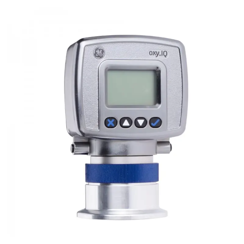
The TENCAN Glove Box Trace Oxygen Analyzer, listed in the glove box accessories range, belongs to this measurement layer. Its role is to indicate trace oxygen in the box atmosphere; it does not remove oxygen, regenerate purification material, or replace a leak-tight enclosure. The current product page should be used to confirm the installed configuration, measurement principle, range, connections, and electrical details. This discussion therefore concentrates on the decisions that apply to any trace oxygen analyzer in a glove box: where it samples, how it is calibrated, what the gas path does to the result, and when a reading is meaningful.
Those decisions matter most when the analyzer is treated as part of the atmosphere-control system rather than as a stand-alone gauge.
The analyzer is a measurement layer, not an atmosphere generator
Purification and measurement solve different problems. A glove box with a gas purification system circulates the atmosphere through material that removes water and oxygen, then returns the treated gas to the enclosure. The analyzer observes the result. If oxygen enters through a glove, a seal, a transfer chamber, or an outgassing sample, the purifier may still be performing its function while the measured concentration rises. Replacing the analyzer with a more sensitive model would not close that path. Likewise, a purifier cannot correct a sample line that admits air downstream of the measurement point.
This separation is easy to lose when a single display is used for both control and verification. A purifier's internal control sensor, if present, supports the purifier's operating logic. An accessory analyzer may serve a different purpose: checking the working atmosphere, confirming recovery after a transfer, logging a trend, or providing an independent alarm. The right arrangement depends on the system architecture and on what decision the number is meant to support.
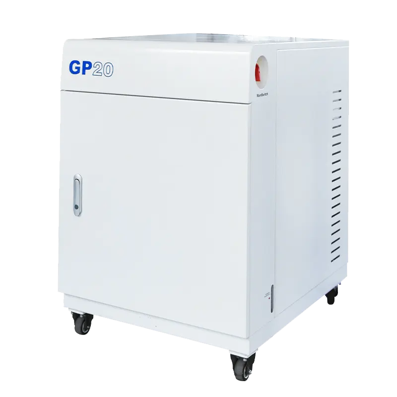
The GP20 Gas Purification System Cabinet is a useful example of why the boundary must be stated clearly. It is a separate gas purification system cabinet, not a complete glove box with an operator workspace. It can be part of a closed loop with a compatible sealed enclosure, but compatibility, connections, control logic, and operating limits must be confirmed for the specific installation. An oxygen analyzer can help show what that loop is doing, yet adding an analyzer does not establish compatibility between a cabinet and an arbitrary box. The GP20 product page should be consulted for its own configuration.
Other accessories also need to be kept in their proper roles. HEPA filtration addresses particles, not oxygen or water vapor. Solvent adsorption addresses certain organic vapors, but it is not a substitute for water and oxygen purification. A pressure gauge describes pressure, not purity. These distinctions matter because a glove box can have several instruments and treatment devices, each answering a different question. A trace oxygen analyzer answers only one: what oxygen concentration does the sampled gas present to the sensor at that moment?
What a trace oxygen reading can and cannot tell you
"Trace" is a relative term. In a glove box, it usually means the oxygen concentration is low compared with ambient air, but the useful measurement window still depends on the application. A researcher working with an air-sensitive material may care about the difference between a stable low reading and a rising trend, while a process engineer may need an alarm at a defined action level. The analyzer should be selected for the range that includes both the normal atmosphere and credible upset conditions, not only the lowest number the display can show.
Range, resolution, accuracy, lower detection limit, response time, and drift are different specifications. Resolution describes the smallest display increment; accuracy describes how close the indication is to a reference value. A display that resolves very small changes does not necessarily measure them with corresponding accuracy. The lower detection limit is not the same as a guaranteed operating level for every gas matrix. Calibration uncertainty and sample-condition effects also belong in the discussion. For those reasons, the last digit on a controller should not be read as an absolute statement about material safety.
Response time has two parts: the sensor's own response and the time required for gas to travel through the sample line. A short sensor response cannot compensate for a long, narrow line with a large dead volume. Conversely, a fast sample path cannot make a slow sensor instantaneous. When the reading changes after a transfer, the delay may be dominated by the sampling system rather than by the box itself. Trend interpretation should therefore include the sample path and the timing of valves, circulation, and transfers.
The gas matrix also matters. Solvent vapors, acidic species, high humidity, and other contaminants can affect some sensor principles, while others may tolerate them differently. The correct answer is not a universal one. It comes from the analyzer's specified gas compatibility, the expected contaminants in the box, and the filtration or sample conditioning placed upstream. A filter intended to protect the sensor must not be assumed to remove oxygen; its purpose is to protect the measurement, not to purify the working atmosphere. Wetted materials, tubing, seals, and fittings should be reviewed with the same care.
Set the measurement window before comparing models
Start with the decision the analyzer must support. Is it confirming a low-oxygen baseline, catching a leak trend, verifying recovery after a transfer, or documenting an atmosphere for a process? Then define the normal range, the upset range, the required response, and the action taken when a limit is crossed. This brief requirement prevents a common error: choosing the lowest advertised range while ignoring accuracy, calibration support, gas compatibility, and integration.
Treat calibration as part of the instrument specification
An oxygen analyzer is only as useful as its calibration. Ask how zero and span checks are performed, which reference gases are required, whether the procedure is performed at the sensor or through the complete sample path, and how often verification is recommended. Calibration gas plumbing should allow the analyzer to see the reference gas without exposing the box to an unintended pressure or atmosphere change. The person responsible for the instrument needs access to the procedure, the records, and the consumables.
Compare the installation envelope, not only the sensor
Two analyzers with similar measurement claims can impose very different installation requirements. Panel space, sample connections, return path, filter access, power, signal outputs, alarm contacts, warm-up behavior, and service clearance all affect whether the instrument can be maintained in a busy laboratory. These are configuration questions, not performance claims, but they often decide whether an analyzer remains calibrated and trustworthy after commissioning.
| Requirement | Why it matters | What to confirm |
|---|---|---|
| Measurement window | Links the instrument to the actual decision | Normal and upset oxygen levels; lower detection limit; resolution versus accuracy |
| Sample conditions | Sample flow, pressure, and gas composition change what the sensor sees | Inlet flow and pressure; temperature; gas compatibility |
| Calibration | Supports traceable readings and drift checks | Reference gases; procedure; interval; records |
| Gas path | Determines delay and exposure | Sample point; line volume; filter; return route |
| Electrical interface | Connects to alarms and records | Outputs; alarm contacts; power; grounding |
Where the sample comes from changes the answer
An analyzer installed at the outlet of a purification loop answers a different question from one sampling near the gloves. The first indicates what the treatment stage is delivering; the second is closer to what an operator or sample sees. A sample point near a transfer chamber may reveal a local disturbance that the main loop dilutes quickly. None of these locations is universally correct. The important step is to state the question, mark the sampling point on the piping diagram, and keep it consistent so that trends remain comparable.
The sample line is part of the measurement. Long runs add delay and can expose the gas to permeation or small leaks. Sharp bends, dead legs, and oversized filters can trap gas and slow recovery. A particle filter may protect the sensor, but a saturated or incorrectly selected filter can also affect response. Tubing material should be compatible with the gas and with any solvent vapor present. If the line can be isolated, the valves and bypass arrangement should be documented so that a "resting" analyzer is not mistaken for a live measurement.
Pressure and flow deserve explicit attention. The analyzer may require a particular sample flow or pressure at its inlet, while the glove box has its own working pressure and pressure-control strategy. Pulling a sample from the box without a return path can change the box pressure; returning gas incorrectly can do the same. A sample pump, regulator, or restrictor may be needed, but it must be selected for the gas and the duty. The safe arrangement is usually to return the sample to the box or to a suitable safe location according to the system design and the manufacturer's instructions.
Before installation, ask a short set of questions:
- Which location represents the atmosphere the application actually depends on?
- What sample flow and pressure does the analyzer expect?
- How is sample gas returned without disturbing box pressure?
- What materials, filters, and isolation valves are in contact with the gas?
These questions are more valuable than a comparison of display features alone. It also helps to decide how the reading will be used. A local display supports manual checks; an analog or digital output supports logging and trend review; alarm contacts support interlock or notification. Each interface introduces its own requirements for power, grounding, signal compatibility, and verification. An alarm should indicate what action follows, not merely illuminate a lamp. If the analyzer is part of a quality record, the data path and calibration records need the same attention as the sensor.
Installation choices that keep the reading trustworthy
A bench demonstration can make an analyzer appear simpler than it is in a glove box. In service, the instrument sits in a gas path that may be isolated, purged, calibrated, or returned to the box. The installation should preserve access to the sample connection, filter, calibration port, and any service item without forcing a long atmosphere upset. Mounting location should avoid vibration, excessive heat, and congestion around the gloves and transfer chamber. These practical details influence whether routine verification actually happens.
Calibration plumbing should be designed before commissioning, not added after the first questionable reading. Reference gas cylinders, regulators, tubing, and vent paths need a defined place. If calibration gas is introduced through the sample line, the volume and purge time determine how long it takes to reach a stable reference. If the analyzer is removed for calibration, the box-side connection must be capped and the sample path protected. The manufacturer's procedure governs the sequence; improvisation can introduce air or create an unsafe pressure condition.
Electrical integration deserves the same discipline. Feedthroughs, signal cables, power supplies, and alarm wiring should be rated for the installation and arranged so that a disconnected cable cannot be mistaken for a valid low reading. Grounding and shielding may affect a low-level signal, and the signal's destination may impose isolation requirements. The supplier should provide the relevant electrical details for the selected configuration. The goal is not merely to make the display work, but to make a failed connection visible and diagnosable.
Maintenance access is a reliability feature. A sensor or filter that is difficult to reach tends to be checked late. Consumables, reference gases, seals, and replacement parts should be identifiable from the documentation. The person who performs verification should know what a passing check looks like and what to do when it fails. A short written routine, tied to the actual sample path, is more effective than a folder of unread specifications. It also makes later troubleshooting less dependent on memory.
The analyzer's location relative to the purification loop should remain visible in the documentation. If a valve is changed, a filter replaced, or a new sampling tee installed, the meaning of the historical trend may change. A simple diagram with the analyzer, sample point, return, isolation valves, and calibration inlet can prevent a future operator from comparing two records that were never equivalent.
When the number rises, or recovery seems slow
A rising oxygen reading is evidence of a change at the sample point, not an automatic diagnosis. The first useful step is to describe the pattern: a step, a ramp, a spike that follows glove movement, a rise after loading, or a slow drift over days. Each pattern suggests a different set of questions. A step that coincides with a valve change points toward the sample path. A rise after a transfer may reflect air carried in or material outgassing. A gradual rise with no process change may involve ingress, purification performance, or the instrument itself.
Recovery time is equally informative. After a transfer, the box volume, circulation rate, purifier condition, material load, and sampling delay all influence how quickly the indicated value returns to its previous level. A large enclosure or a heavily loaded sample can take longer than a small, lightly loaded one. A slow return is not proof of a faulty purifier, just as a rapid return is not proof that the atmosphere is suitable for every material. The analyzer reports oxygen at its location; the process requirement determines how much deviation is acceptable.
Troubleshooting should separate the enclosure, the purification loop, and the measurement chain. Check whether the reading changes when the sample flow or valve position changes. Review purifier status and regeneration records if applicable. Inspect gloves, seals, ports, and transfer procedures according to the system's safety plan. If a second calibrated instrument is available, a comparison at a defined point can help distinguish a local sensor issue from a box-wide change. None of these checks replaces the equipment manufacturer's instructions.
Water and oxygen are separate measurements. A low oxygen reading does not establish a low water concentration, and a water analyzer does not verify oxygen. Solvent vapor may be present without appearing on either instrument. This is why a glove box atmosphere should be described with the measurements that were actually made, not with a general claim of purity. It is also why an accessory should be selected for the specific variable it is meant to monitor.
If a reading remains inconsistent after basic checks, document the conditions and contact the supplier with specifics: sample point, flow, pressure, gas composition, recent calibration, observed pattern, and any maintenance or valve changes. That information supports a technical conversation and avoids assuming a sensor failure before the sample path and operating state have been reviewed.
Configuration checklist before selecting an analyzer
The selection process should end with a configuration that can be installed, calibrated, and interpreted. Start with the application: what material or process is being protected, what oxygen level matters, what change triggers action, and who reviews the trend. Then describe the box and gas loop: volume, working pressure, circulation arrangement, available sampling points, expected contaminants, and the way gas can be returned. These facts define the analyzer's duty more accurately than a generic request for a "trace oxygen analyzer."
- Target and upset oxygen ranges, with the decision associated with each.
- Required resolution, accuracy, response time, and calibration support.
- Gas composition, solvent or acid vapors, humidity, and filter needs.
- Sample flow, pressure, temperature, connection type, and return path.
- Panel space, power, signal outputs, alarms, and data logging.
- Calibration gas availability, procedure, frequency, and records.
- Service access, consumables, documentation, and spare parts.
- Compatibility with the existing enclosure and purification equipment.
Suppliers need enough information to check compatibility rather than guess. Provide a piping sketch, the expected operating pressure and flow, the gas and contaminant list, the desired electrical interface, and the conditions under which the reading will be trusted. Ask explicitly whether the proposed analyzer is suitable for the sample gas and whether any filter, regulator, pump, or return arrangement is required. For a separate purification cabinet such as the GP20, confirm the loop interface and control assumptions with its own documentation; do not infer compatibility from the presence of an oxygen analyzer.
A trace oxygen analyzer earns its place when its reading can be traced to a known sample point, a valid calibration, and a defined response. The instrument does not create a low-oxygen atmosphere, and it does not prove that every material inside the box is protected. It provides evidence. Good selection makes that evidence specific enough to act on, and good installation keeps it comparable from one week to the next.
