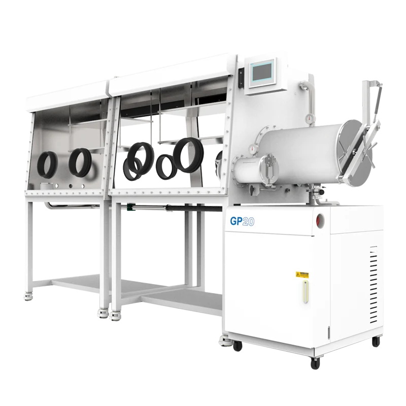
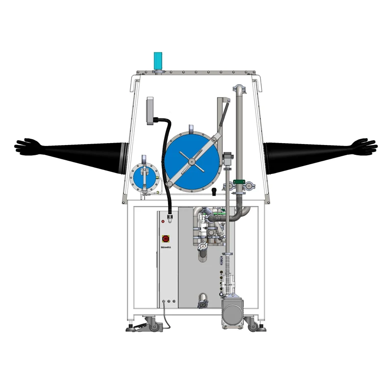
Choosing a purification glove box usually begins as a question about size and quickly becomes a question about the atmosphere. Two researchers who need to assemble cells on the same day, a deposition step that must run overnight under inert gas, a sample that has to move between an oven and a characterization tool without ever seeing air — each of these requirements pushes the enclosure toward more working positions, more transfer capacity, and a purification loop that can keep up with the traffic.
The four-station, double-sided split-type glove box with gas purification system is a configuration built around exactly that kind of continuous, multi-operator workflow. It combines four working positions with access from two sides, and it separates the enclosure from the gas purification hardware. What follows is a practical look at what this layout solves, where the trade-offs sit, and which details a buyer should pin down — including the role of a KF40 electrical test lead feedthrough when measurements have to be made inside the box rather than on a sample that has already been exposed to air.
What the Purification Function Actually Does
A gas purification glove box is a closed system in two senses. The enclosure is sealed from the surrounding room, and the atmosphere inside it is circulated and cleaned rather than used once and discarded. Gas is drawn out of the working space, pushed through purification media that captures moisture and oxygen, and returned to the box. Because the same gas inventory keeps moving, the loop can hold an atmosphere steady for long periods, which is what makes an overnight experiment or a multi-day sample campaign practical.
In a split-type design, that hardware does not sit underneath or behind the glove ports. The purification cabinet is a separate unit connected to the enclosure by ducting and cable runs. The consequences are worth spelling out: the working enclosure can be kept to a compact footprint while the purifier, blower, valves and controls occupy a service position where they can be reached without leaning over the glove ports; heat and noise from the circulation equipment stay out of the operator's immediate workspace; and the enclosure itself can be sited to suit the room rather than to suit the machine. The trade-off is a dependency on the connection between the two halves, which should be kept short and treated as a maintenance item.
Three gas roles are usually distinguished in this class of equipment, and mixing them up is a common source of confusion during commissioning: working gas, which is the inert atmosphere the samples live in; control or actuating gas, used to drive valves and pneumatic functions; and regeneration gas, used when the purification media is refreshed. Whether a given installation needs separate supply lines for all three depends on the configuration and should be confirmed rather than assumed.
Circulation rather than one-way purging
A simpler inert enclosure can be managed by repeatedly evacuating and refilling with inert gas, or by bleeding gas through the box. Both approaches work, and both consume gas continuously. A purification loop is different in kind: it treats the atmosphere as a resource to be maintained. The advantage appears when the box is used often, because purging costs scale with every door opening and every experiment, while purification costs scale with the media's capacity and the leak rate of the enclosure, which are largely fixed. That is why purification systems dominate in laboratories where samples are handled daily.
Regeneration is a maintenance state, not an operating mode
Purification media does not last forever. Once moisture and oxygen have loaded the media, the column has to be regenerated: heated while a gas stream carries the released species away, then cooled and returned to service. During that window the capacity of the loop is reduced, and the atmosphere can drift if the box is heavily used. Two consequences follow. First, regeneration should be scheduled around experiments rather than during them. Second, the number of purification columns matters to workflow: a system with more than one column can in principle be regenerated in stages while the remaining column carries the load, but whether a specific configuration supports that is a specification question for the supplier, not something to infer from a product name. Regeneration conditions — gas composition, temperature profile and duration — belong to the manufacturer's procedure and should never be improvised.
Why the Layout — Four Stations, Two Sides, Split Frame — Matters
The name of this system packs three independent design decisions into one line: how many people can work at once, from which side they work, and how the enclosure is related to the rest of the hardware. Each decision trades something away.
Four stations: parallel work without parallel atmospheres
A station is a working position at the front of the box — in practice, a pair of glove ports together with the floor area, lighting and services that go with it. Four stations means the enclosure is sized for several simultaneous tasks: one person assembling coin cells, another preparing a perovskite precursor, a third weighing a moisture-sensitive catalyst, a fourth running a transfer in or out. The advantage is not simply more room. It is that a shared atmosphere removes the need for several small boxes, each with its own purification hardware, its own monitoring and its own transfer logistics.
The trade-off is that everything downstream scales with the box. More stations means a larger internal volume to keep clean, more glove ports to seal and maintain, and more opportunities per hour for someone to leave a port open or a transfer door ajar. Interior fittings — shelving, gas lines, electrical rails, instrument stands — have to be planned early, because retrofitting a large enclosure after it is under atmosphere is far more disruptive than agreeing on the layout beforehand. A useful exercise is to sketch the intended workflow on paper: which station holds which instrument, where samples enter and leave, and where an operator stands. If two of those positions would be occupied by the same person on the same day, four stations may be more than the work requires.
Double-sided access: two operator groups, one shared atmosphere
A double-sided enclosure puts glove ports on both long faces, and that single change alters laboratory organization more than any number on a datasheet. Two people can work back-to-back on the same atmosphere without reaching over each other; a preparation bench on one side and an analytical bench on the other can share samples without a separate transfer step; a supervisor or trainee can watch and assist from the opposite side without entering the working position.
It also changes circulation. A larger internal volume with port pairs on two faces means the atmosphere has more surface to exchange heat with and more paths to leak. If you expect to run a moisture-sensitive process at one station while a transfer door is opened repeatedly at the other, ask how the circulation path is arranged before assuming that a single loop reading describes the whole enclosure. Monitors report the atmosphere at their own sampling point; they do not map the box.
Split construction: service access, floor plan, and decoupling
Keeping the purification cabinet separate from the enclosure is a workflow decision as much as an engineering one. Service work — changing media, checking valves, replacing blower components — happens at the cabinet, not on top of the box, so the working face stays clear. The heat and noise of circulation move away from the operators. The enclosure can be positioned against a wall, in a corner, or across a doorway, with ducting taking up the slack. And a split arrangement makes it easier to treat the enclosure and the purifier as separate assets when the laboratory is reorganized later.
The counterpart is that a longer run between purifier and box is not free: it adds volume to the loop and gives the circulated gas more distance over which to pick up contamination from imperfect seals. When planning the layout, keep the run as short as the room allows, and treat every joint on that path as a routine inspection point.
Transfer, Antechambers, and the Real Cost of Every Sample Entry
Sample transfer is where atmosphere control is most often lost, and it is worth thinking about before choosing station count. Most purification glove boxes move material in and out through an antechamber, sometimes called a transfer chamber or airlock. A sample is placed inside, the chamber is evacuated and refilled with inert gas, and only then does the inner door open onto the main enclosure.
Each cycle has a cost in atmosphere, in time and in gas. A vacuum-and-refill cycle removes the air that came in with the sample; repeating it improves the result but lengthens the operation. Large antechambers take longer to cycle and consume more gas per transfer than small ones, because there is more volume to evacuate and refill. For glove boxes used in battery or perovskite work, where small samples enter and leave frequently, the throughput of the transfer path can matter more to daily productivity than the size of the main enclosure.
Two practical points follow. First, match the antechamber to the largest object you realistically expect to bring in — an instrument in a crate, a fixture, a small furnace tube — and accept the cycling cost that comes with it rather than planning a string of transfers that do not fit. Second, plan the flow of material so that entries and exits are batched. Ten small items transferred together cost roughly one cycle; ten separate cycles cost ten times the gas and ten times the disturbance to the atmosphere.
Gloves themselves are part of the transfer equation. Every glove is a permeable membrane and a mechanical seal at the same time. Material compatibility, thickness and length determine how the glove behaves with the solvents and reagents you plan to use, how quickly it degrades, and how much it interferes with handling. That choice should be made against the chemistry in your process, not against a generic preference.
Getting Signals In and Out: Feedthroughs and In-Situ Electrical Testing
Once samples live inside an inert atmosphere, the next question is whether measurements happen inside too. Taking a sample out to measure it defeats the purpose: a lithium metal surface, a perovskite film or an air-sensitive catalyst can change within the seconds it takes to move from the antechamber to an instrument. The usual answer is to bring the instrument — or at least its connections — to the sample.
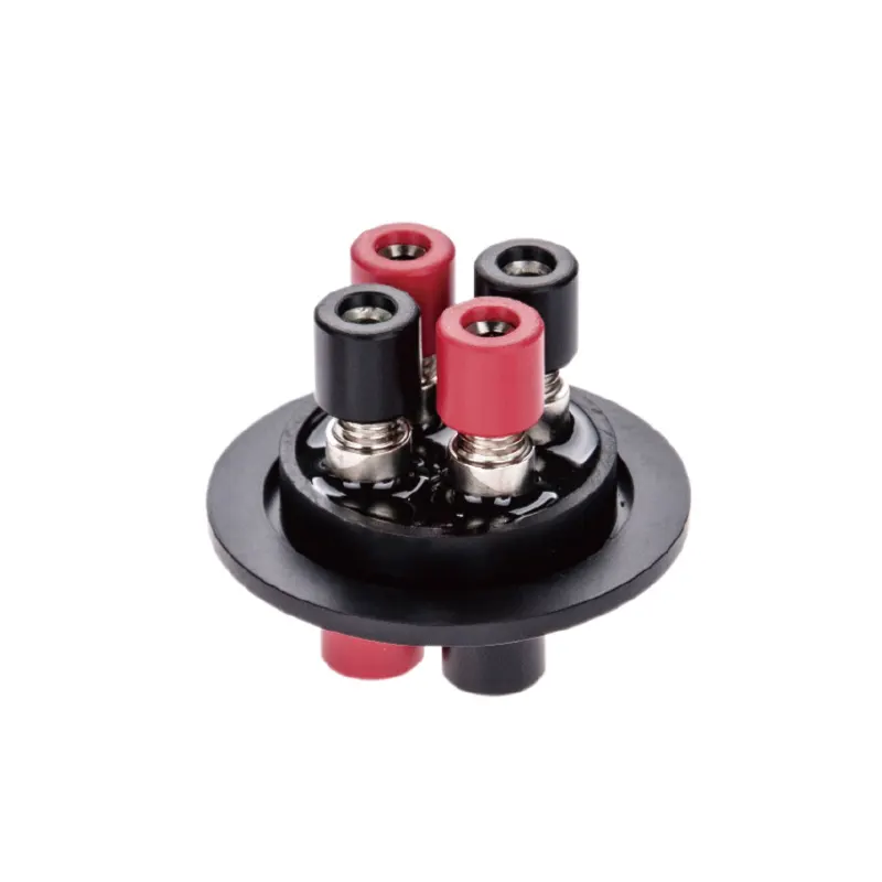
That is what a feedthrough does. It is a sealed penetration through the enclosure wall that carries something across the boundary: electrical conductors, thermocouple wires, gas lines, signal cables or fluid paths. For electrical testing, the relevant part is a lead feedthrough, and the KF40 electrical test lead feedthrough is an example of the type: electrical test leads passed through a flange-mounted fitting so that a cell, sensor or device inside the box can be connected to instrumentation outside it.
Why the flange standard matters
KF40 refers to a nominal 40 bore in the KF quick-flange family, a widely used vacuum flange standard with a centring ring and clamp. Flange-mounted accessories are attractive because they attach at defined ports rather than requiring a custom opening, and because a clamped joint can be opened and reseated during maintenance. The choice of flange is therefore partly about how the enclosure was built: which ports exist, where they are, and what is already occupying them. Before ordering any feedthrough, list the spare ports on your enclosure and confirm their standard. A feedthrough that does not match an available port solves nothing.
Selection factors for an electrical feedthrough
The specification that matters is the one your measurement imposes. Conductor count and gauge determine how many signals you can pass and how much current each can carry. Insulation material decides compatibility with the temperature and chemistry near the port. The way the leads are terminated, inside and outside, decides how easy it is to connect a test rig without stressing the seal. For low-level signals, shielding and grounding practice inside the box often matter more than the feedthrough itself, because a short run of unshielded lead in a noisy electrical environment can swamp a small measurement.
Leak integrity is the other half of the equation. Every feedthrough is a potential leak path, and the seal is only as good as its installation: flange surfaces must be clean and undamaged, the centring ring correctly seated, and the clamp tightened consistently. A feedthrough that has been opened and closed many times should be treated as a wear item and checked as part of routine maintenance. Ratings, materials and available lead configurations vary, so the electrical and temperature limits of a specific feedthrough should be confirmed with the supplier against your intended test rather than assumed from the flange size.
Monitoring: What Analyzers Can and Cannot Tell You
Moisture and oxygen analyzers are the instruments operators look at most, and they are also the most frequently misread. An analyzer measures the atmosphere at its sampling point. It does not purify the atmosphere, and it does not necessarily represent the whole enclosure. Two failure modes are common: treating a single reading as a map of the box, and treating a slow recovery after a disturbance as proof of a fault.
Consider what happens when a transfer chamber is cycled or a port is left open. The reading rises. When the loop is running normally the reading falls again, but the shape of that recovery curve depends on the volume of the box, the circulation rate, the position of the sampling point, and how much of the disturbance actually reached the sensor. A large, multi-station, double-sided enclosure has more internal volume and more surface area than a small single-station box, so recovery is inherently slower for the same leak or load. That is a design consequence, not evidence of a defect.
Distinguishing a leak from a load is the useful diagnostic habit. A load is a finite amount of moisture or oxygen introduced by a specific event — a sample, a solvent bottle, a glove change — and the reading recovers as the loop removes it. A leak is continuous: the reading settles at a level determined by the balance between leak rate and purification capacity, and never returns to the value it held before. If a reading plateaus rather than recovers, look for a door not fully seated, a glove with a pinhole, a recently disturbed flange or feedthrough, or a joint in the ducting between enclosure and purifier.
Analyzer specifications deserve the same care as the rest of the system. Resolution is the smallest change an instrument can display; accuracy is how close the displayed value is to the truth. A display with fine resolution can be less accurate than a coarser one, and calibration drift affects both. Instrument readings are therefore most useful as trends and early warnings, not as absolute guarantees of sample condition.
Applications That Fit This Configuration
The four-station, double-sided layout with a purification loop suits work where air and moisture sensitivity are continuous rather than occasional, and where several people share the same equipment. Typical candidates include lithium and solid-state battery materials, where metal anodes, sulfide electrolytes and some cathode chemistries react quickly with moisture; perovskite and OLED materials, where film quality depends on the atmosphere during preparation and handling; air-sensitive organometallic and catalyst chemistry; and advanced materials research where samples must be kept under inert gas between processing steps. Handling and post-processing in additive manufacturing can also fit, when the concern is oxidation of a reactive powder or part surface.
It is important to be precise about what an inert atmosphere is and is not. A purification glove box controls oxygen, moisture and, to a degree, the gas composition around the sample. It is not a cleanroom with a defined particle classification, not a biological safety cabinet, and not a containment enclosure certified for dangerous materials; those are separate requirements with separate standards. Likewise, an inert gas is not inert to everything: some samples react with nitrogen, some with trace impurities in a supply gas, and some solvents attack gloves or seals. Confirm compatibility for your specific chemistry before assuming that any box solves it.
Configuration Checklist Before You Request a Quotation
The fastest way to a usable specification is to describe the work rather than the equipment. Suppliers can translate a workflow into a configuration; they cannot guess it from a station count. The following items cover most of what determines whether a four-station, double-sided, split-type purification box is the right answer or an oversized one.
- Workflow: how many operators use the box at the same time, and whether they work on the same task or on independent ones.
- Sample logistics: what enters and leaves, how often, and the largest and heaviest item that must fit through the transfer path.
- Chemistry: solvents, reagents and materials that will contact gloves, seals, windows and interior surfaces, together with their temperature range.
- Instrumentation: which tools stay inside permanently, and what they need — power, signal, gas, cooling, mechanical support.
- Feedthrough requirements: number of electrical signals, expected current and voltage, signal level and shielding needs, and which flange standard the available ports use.
- Atmosphere targets: the oxygen and moisture levels your process actually needs during operation, and how much drift is tolerable between transfers.
- Facilities: floor space, ceiling height, gas supply, electrical service, and the distance between the enclosure location and the purification cabinet.
- Service expectations: who will regenerate purification media, how often the loop is expected to run, and what local support exists.
Finally, ask for the operating documents — installation requirements, start-up and regeneration procedures, and maintenance intervals — as part of the quotation package, and read them before the equipment is positioned. The four-station double-sided split-type glove box with gas purification system is a configuration, not an installation: the layout, the transfer path, and the way the purification loop is serviced determine how well it performs in your laboratory.