
A KF vacuum butterfly valve is a compact isolation valve with KF clamp-type connections, installed in the vacuum path of a glove box or its transfer chamber to open, close, or partly restrict flow between a chamber and a pump, exhaust line, or service branch. It does not create the inert atmosphere and it does not remove oxygen or moisture. Its job is narrower: make the vacuum side controllable, serviceable, and easier to isolate. That distinction matters because atmosphere quality, chamber evacuation, and pump protection are separate functions in a sealed glove box system.
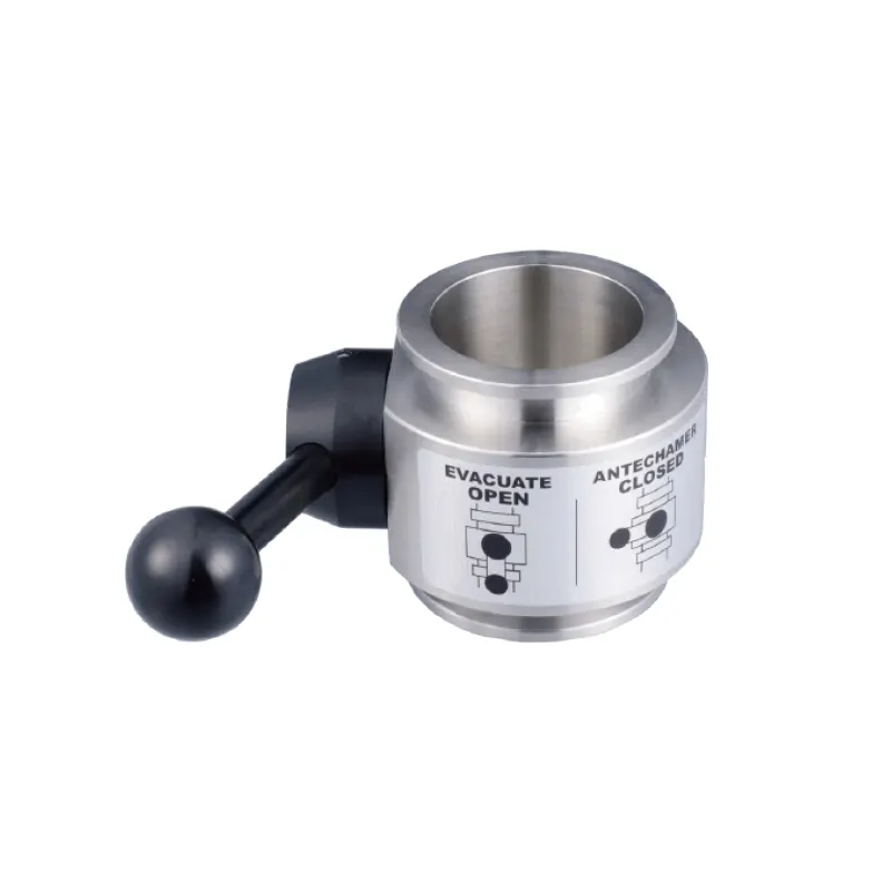
The current product listing for the KF Vacuum Butterfly Valve identifies the component as a KF-flanged vacuum valve. The selection questions below apply whether the valve is used on a small transfer chamber or on a larger vacuum manifold, but the final check should always be against the actual datasheet and the system drawing.
What Does a KF Vacuum Butterfly Valve Do?
A butterfly valve uses a circular disc mounted on a shaft. In the open position the disc is turned so that it lies roughly parallel to the flow; in the closed position it turns across the bore and seats against the body. Partial rotation changes the open area and therefore the conductance between the two sides of the line. In vacuum service, the disc and shaft must work under a pressure difference, so the stem seal, seat, and body stiffness matter as much as the bore size.
KF is a clamp-type flange connection. Mating flanges are brought together over a centering ring and seal, then held by a clamp. This is why KF hardware is common on glove box vacuum lines that need frequent assembly, pump changes, or cleaning. The valve does not set the flange standard by itself; the valve flange, centering ring, seal, and mating line must all match.
A butterfly valve is often chosen for isolation and for coarse flow adjustment. It is not a precision mass-flow controller, and a partially open position should not be treated as a calibrated process setpoint unless the flow has been characterized. It also is not a check valve, a pressure-relief device, or an automatic safety interlock. Those functions require separate components or controls.
Where Does It Fit in the Vacuum Side of a Glove Box?
Vacuum lines are utility paths. A valve may isolate a transfer chamber from a pump, separate one section of a manifold during service, or close a branch that is not in use. It may sit near the pump to limit exposure of the pump to a chamber, or near a chamber to allow that chamber to be worked on without disturbing the rest of the vacuum circuit. The useful question is not simply where a valve can be fitted, but which section needs independent isolation and which section must remain connected for safe operation.
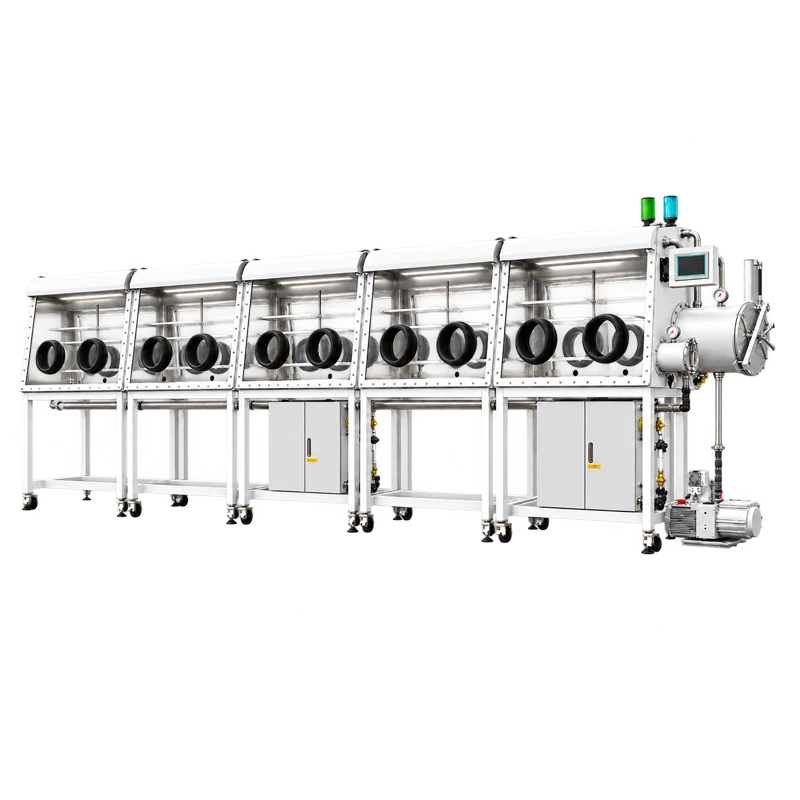
Glove boxes with gas purification systems have a separate recirculating atmosphere loop. That loop moves the working gas through purifier columns and monitoring instruments, and it is the purification system, not a vacuum valve, that removes moisture and oxygen from the atmosphere. A purification glove box can also have transfer chambers and vacuum pumps, but the exact valve arrangement depends on the model and should be checked on the system drawing. For an example of a larger sealed system that combines multiple workstations with a purification system, see the ten-station double-sided split-type glove box with gas purification system. The presence of such a system does not, by itself, confirm that a particular KF valve is fitted or compatible.
A vacuum isolation valve is not a vent valve. Closing a line and venting a chamber are different operations. Venting requires a controlled gas inlet and a defined vent path; a valve on the pump line does not provide that function unless the system has been designed and documented that way.
How the Valve Behaves Under Vacuum
When one side of the valve is under vacuum and the other is at a higher pressure, the disc experiences a load. A manual handle must supply enough torque to move the disc against that load, and an automated actuator must be sized for the same condition. A valve that opens easily on a bench may behave differently when installed in a line with a pressure difference, so actuator selection and operating procedure should be based on the installed duty rather than on the valve alone.
The disc also affects conductance. In the open position, the flow path should be as unobstructed as the design allows; in the closed position, the seat and stem seal define how well the two sides are separated. A partially open butterfly valve can be useful for rough throttling, but it is a poor substitute for a metering valve when repeatable, low-flow control is required. If a process depends on a specific pump-down rate, the valve position, line volume, pump performance, and conductance all interact.
Vacuum service also makes stem sealing important. The shaft passes through the body, so the design must limit leakage around the stem while still allowing rotation. Seal material, surface finish, and contamination all affect that boundary. For this reason, a valve used on a clean vacuum line should not be assumed to perform the same way after exposure to condensable vapors, particles, or aggressive chemicals.
Which Configurations and Connections Matter?
The first configuration check is the KF flange size and the mating hardware. The valve flange, centering ring, seal, clamp, and adjacent tube or chamber flange must form a complete connection. A nominal size match is necessary but not sufficient if the mating part has a different profile, if the clamp is missing, or if the seal material is unsuitable for the process. The connection should be assembled without forcing the parts into alignment.
The second check is actuation. A manual valve is simple and direct, but it requires access to the handle and enough clearance for rotation. An automated valve needs a defined actuator, control signal, position feedback, and a plan for what happens if control power or instrument air is lost. Automated operation should not be added merely for convenience; it should match the system's interlock philosophy and the operator's ability to respond to a fault.
The third check is the wetted path. Body material, disc material, shaft material, and seal material all contact the gas or vapor. A seal that is acceptable for dry nitrogen may be a poor choice for solvent vapor or for a cleaning agent. Similarly, a valve that works well in a clean, dry vacuum line may trap particles or condensate in a dirtier process. Material compatibility and cleanability should be confirmed before installation, not after the valve is in service.
Which Specifications Should You Check Before Ordering?
- Flange and connection: confirm the KF size, flange profile, clamp, centering ring, and seal. Check that the adjacent line uses the same connection system.
- Vacuum range: compare the valve rating with the actual operating pressure and with any pressure difference across the disc. A line pressure specification is not the same as a differential-pressure rating.
- Leak performance: ask what leakage or isolation performance is documented for the valve in the intended condition. Do not infer a leak rate from the flange name alone.
- Materials and seals: verify the body, disc, shaft, and seal materials against the gas, vapor, and cleaning agents in use. Consider oxygen compatibility where relevant.
- Flow behavior: check conductance in the open position and the intended use of partial opening. If repeatable throttling is needed, confirm that the valve and actuator can deliver it.
- Actuation and controls: define manual or automated operation, control voltage, position indication, and failure behavior. Confirm that the actuator does not interfere with nearby hardware.
- Cleanliness and maintenance: confirm cleaning requirements, replaceable parts, and access for inspection. A valve that cannot be serviced in place may create unnecessary downtime.
Do not compare a valve's vacuum rating with a glove box's oxygen or moisture specification. One is a pressure and leakage characteristic; the other is an atmosphere composition measurement. A valve may be suitable for a vacuum line yet have no role in reaching a particular oxygen or moisture level.
Where Is It Suitable, and What Are Its Limits?
A KF vacuum butterfly valve is suitable where a KF-connected line needs compact isolation at the documented vacuum level. Typical uses include pump isolation, transfer chamber evacuation lines, manifold sectioning, and service branches that must be closed while another part of the system remains available. The valve is also useful when the vacuum circuit needs a clear open path during normal operation and a simple closed position for maintenance.
The limits are just as important as the uses. The valve is not a gas purifier, an oxygen or moisture analyzer, a HEPA filter, a solvent trap, a sterile barrier, or a pressure regulator. It does not establish a cleanroom classification, biological safety, or hazardous-duty approval. It also does not by itself establish a low-oxygen or low-moisture atmosphere. Those outcomes depend on the complete glove box design, the purifier, the transfer procedure, the leak integrity of the enclosure, and the monitoring system.
Compatibility should never be assumed from a shared supplier or a shared website. A valve and a glove box may both be offered for laboratory work, but the valve still has to match the line size, vacuum duty, gas exposure, and control architecture of that specific box. For aggressive vapors, oxygen service, high particulate loads, or ultra-high vacuum, confirm the materials and design with the actual specification. A valve with elastomer seals may be unsuitable where a different seal or an all-metal boundary is required.
How Should You Select and Integrate One?
- Define the function. Decide whether the valve is for isolation, coarse throttling, pump protection, or service sectioning. A valve that must do two jobs may need a different design or an additional component.
- Match the line. Measure the existing KF connection and confirm the clamp, centering ring, seal, and clearance. Do not rely on a photograph or a nominal size alone.
- Confirm the vacuum duty. Check the operating pressure, the pressure difference across the closed disc, and the pump's behavior. Confirm that the actuator can move the valve under the worst expected differential.
- Check the materials. Review the gas, solvent, cleaning agent, and any process condensate. Select the seal and body material for the actual exposure, not for the cleanest assumed condition.
- Plan the controls. For automated operation, define the signal, position feedback, interlocks, and failure position. For manual operation, confirm that the handle can be reached and that opening or closing will not disturb adjacent lines.
- Install and verify. Support the line, align the flanges, tighten the clamp correctly, and perform an appropriate leak check after assembly. Record the installed orientation and any maintenance access requirements.
- Document the boundary. Mark what the valve isolates and what it does not. Keep the vent path, pump path, and purification loop clearly separated in the system drawing.
The KF Vacuum Butterfly Valve should be selected only after those conditions are known. The product name tells you the general family and connection style; it does not replace a review of the flange, seal, vacuum rating, and actuation details for the intended line.
Frequently Asked Questions
Does a KF vacuum butterfly valve purify the atmosphere inside a glove box?
No. The valve controls flow in a vacuum line. Atmosphere purification is performed by the glove box purifier and its circulation system, while oxygen and moisture levels are measured by separate instruments. A valve can isolate a line, but it cannot remove contaminants from the working gas.
Can closing the valve directly lower oxygen and moisture?
No. Closing a valve may isolate a chamber or a pump path, but it does not replace evacuation, inert gas purging, or purification. The atmosphere quality of the glove box depends on the complete procedure and the condition of the enclosure, not on the valve alone.
How can I check whether a KF connection will fit?
Compare the nominal KF size, flange profile, centering ring, seal, and clamp with the mating parts. Check the valve datasheet and the existing line drawing. Parts should assemble smoothly; a clamp should not be used to pull mismatched flanges together.
Does every glove box need a KF vacuum butterfly valve?
No. The need depends on the vacuum architecture. Some systems use other isolation methods, some have more than one vacuum branch, and some transfer chambers are not pumped in the same way. Review the system drawing and the intended maintenance plan before adding a valve.
Can the valve be used as a vent valve?
Do not assume so. Venting requires a controlled gas inlet and a defined vent path. A valve installed in a vacuum isolation line is not automatically a vent control, and using it incorrectly can disturb the chamber atmosphere or the pump condition.
The practical rule is to treat the KF vacuum butterfly valve as a defined piece of the vacuum circuit, not as a general atmosphere-control device. Confirm the connection, the vacuum duty, the seal material, and the control method; then integrate it so that isolation, venting, and purification remain separate, documented functions.
