
A slow return to baseline is a system-level signal
An operator closes the transfer chamber, opens the inner door, moves a sample onto the work surface, and watches the oxygen and moisture display. The numbers rise, as expected. What follows is the interesting part: instead of dropping back within the familiar interval, the readings drift down over a period that feels much longer than usual, or they settle slightly above the baseline the lab has grown used to. The instinctive reaction is to blame the purifier. In most cases the purifier is doing exactly what it was designed to do, and the delay is being generated somewhere else in the chain — in the volume of air that entered, in the material that entered with the sample, in the way gas moves through a two-station enclosure, or in the instrument that is reporting the result.
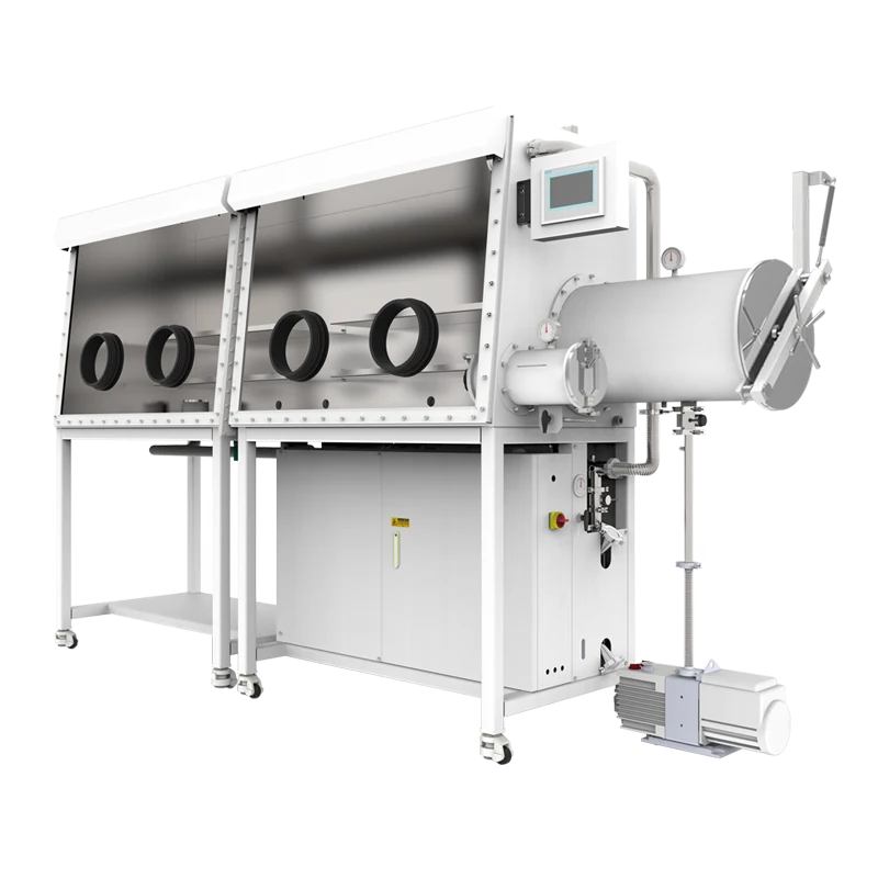
This matters for a two-station single-sided split-type glove box with gas purification system because the layout multiplies the number of places where the recovery curve can be shaped. Two working positions share one purification loop, one set of monitoring points and an enclosure assembled from more than one section. Each of those features is an advantage in daily use, and each adds a variable to interpret when the atmosphere takes longer than expected to come back into specification. Treating the recovery curve as a system-level signal, rather than a single-component fault, is the fastest route to a correct diagnosis — and, before purchase, to a correctly specified box.
Three sources of water and oxygen after the door closes
Almost every slow recovery can be traced to one of three contributions, and separating them is the first useful step. They differ in magnitude, in how long they persist, and in what the operator can do about them.
Air carried in with the load
When a transfer chamber is opened to the room, it fills with ambient air. If the chamber is then closed and immediately equalised with the box atmosphere, that air is pushed straight into the working volume; the purifier must remove the moisture and oxygen it contains while the box is already in use. A proper cycle first evacuates and then refills with working gas, and repeating that dilution several times reduces the residual contaminant load substantially. This is why the recovery curve is steeper and shorter when the antechamber is cycled patiently and shallower when it is cycled quickly to save time. Boxes supplied without a vacuum-capable transfer chamber, or with a simple pass box, rely on dilution alone and will always show a larger disturbance per transfer.
Outgassing from samples, gloves and surfaces
The second contribution arrives with the object itself. Powders with high surface area, porous ceramics, lithium salts, some polymers, solvent-wet substrates and unsealed cells all release water or oxygen-bearing species after they are placed inside. The same is true of gloves and of any material that has just been brought in from room air. Outgassing is a decaying source rather than a step change: it is highest in the minutes after the inner door closes and then tapers. If the readings fall quickly at first and then flatten into a long tail above baseline, outgassing is usually the dominant term, and the answer is a longer purge before the material is exposed, or a preliminary dry-down step outside the box.
Continuous ingress through seals, gloves and ports
The third contribution never stops. Every glove, glove port, door gasket, weld, valve stem, feedthrough and instrument fitting is a potential leak path, and the resulting ingress is roughly constant. On its own it produces a steady state the purifier can absorb. Combined with a transfer, it raises the level that the loop must work against, which is why a box with marginal seals shows a normal recovery after a small transfer but a slow, incomplete recovery after a heavy one. Leak-related behaviour is also the easiest to distinguish: the baseline itself creeps upward during idle periods, especially overnight, without any operator activity to explain it.
How a two-station split-type layout shapes the curve
The physical arrangement of the enclosure determines how quickly a local disturbance becomes a global one, and how much clean gas the loop must push before the last stagnant region is refreshed.
Two workstations served by one loop
Two working positions along a single working face give two people room to work, or one person room to spread out a process. They also mean that a transfer made at one station disturbs a volume that extends to the other. Mixing does not happen instantly. Gas entering at the supply point travels along the enclosure, and regions far from the inlet — the far end of the second station, the corners below the work surface, the space above the ports — exchange more slowly. A disturbance created at the near station is therefore detected by the analyser before it has been fully diluted at the far station. Recovery appears slow even when the purifier is removing water and oxygen at its normal rate, because part of the enclosure is still contributing contaminants to the circulating stream.
Where a process requires one station to stay clean while the other is loaded, the layout should be discussed with the supplier at the specification stage: the position of supply and return points, the number and location of monitoring points, and whether a physical division between the two working positions is available all affect how independently the two sides behave.
What split-type construction changes
A split-type enclosure is assembled from separate sections rather than built as one welded shell. The practical reason is access: sections can be carried through a normal door, lifted in a service elevator and assembled in the room where the box will be used, which is often the only feasible route into a basement laboratory or an upper floor. The consequence is a different set of joints. Each joint between sections is a seal that must be correctly seated and correctly tightened, and the joint faces are additional places where the interior geometry changes and gas can linger. Split construction is not a weakness; it is a design choice with a maintenance implication — the joints deserve a place on the periodic leak check, and the order of assembly and tightening should follow the supplier's instructions rather than workshop habit.
The purifier, the blower and the pipework: which one sets the pace
Once air and outgassing are accounted for, the remaining question is how fast the loop can remove what is present. Three elements determine that, and they are frequently confused with one another.
The purifier is a rate device, not a switch
A purification column removes water and oxygen from the gas passing through it. Its capacity sets how much contaminant can be absorbed before regeneration is required; its kinetics and the flow rate through it set how fast a given amount is removed. The two are different specifications, and only the second governs recovery speed. A box whose purifier is approaching saturation can still hold an acceptable baseline overnight, when ingress is low, yet respond sluggishly to a large disturbance. If the recovery time has lengthened gradually over weeks while the idle baseline has remained acceptable, purifier condition and the time since the last regeneration cycle belong on the checklist alongside leaks.
Circulation and stagnant volume
The blower or circulator moves gas from the enclosure, through the column and back. Recovery is limited by how many enclosure volumes per unit time are exchanged and by whether the flow actually reaches every region. Duct openings that are obstructed by stored items, work surfaces crowded with equipment, or a return line positioned in a corner of a two-station box all produce short-circuiting: clean gas passes from supply to return without sweeping the volume where the contaminant sits. This is the most common reason a box that once recovered briskly now recovers slowly without any change in the purifier.
Regeneration is not purification
The regeneration step drives absorbed water out of the purification material so the column can be used again. During regeneration the loop is not performing its normal duty, and the box may be isolated or held on a different gas path. Confusing regeneration with purification leads to two errors: expecting the atmosphere to improve during a regeneration cycle, and treating a completed regeneration as proof that the purifier is at full capacity. If a slow recovery follows a regeneration, the useful questions are whether the cycle completed normally, whether the box was properly isolated during it, and whether the column was overdue.
Reading the instrument, not just the number
Some apparently slow recoveries are real; others are an artefact of how the atmosphere is measured. An analyser measures; it does not purify. Where its sample is drawn from matters: a point close to the transfer chamber sees the disturbance first and the recovery last, while a point on the return line sees an averaged value that can look reassuringly flat. Response time, which is a function of the sensor principle, the sample line length and any filter in the path, adds a lag that the operator perceives as slow recovery. A short sample line with minimal dead volume gives a faster and more representative reading.
Resolution is also not accuracy. A display that resolves to a fine increment does not guarantee that the value is correct within that increment, and an uncalibrated sensor can hold a reading above baseline long after the atmosphere has recovered — or report a comfortable value while the box is worse than it appears. Where a reading is used to release material into a process, the calibration interval, the calibration gas and the sensor's stated measuring range should all be known. If a value in the documentation is ambiguous, or its unit or reference condition is unclear, the right move is to ask for the condition under which it applies rather than to design a process around it.
Getting data out without letting air in: the KF40 Ethernet feedthrough
Instruments inside a purifying box increasingly need to talk to equipment outside it: a data logger on the bench, a balance or analyser reporting to a lab network, a camera monitoring a sample, or a controller that must be reached remotely. Opening the box to run a cable is not an option, and routing a cable through a door gasket compromises the seal it passes. A feedthrough solves this by providing a sealed electrical or signal path through the enclosure wall.
The KF40 Ethernet feedthrough is a flange-mounted connector that carries an Ethernet connection through a KF40 port. For a two-station box the practical value is that network-connected instruments can be placed at either workstation while the data path stays outside the enclosure, and the connection can be added at a standard port rather than requiring a bespoke penetration. Several points deserve confirmation before ordering. The KF40 designation describes the flange interface, not the electrical performance: the connector type and category, the number of contacts, the cable length on each side and the sealing method are separate specifications that should be matched to the equipment being connected. The feedthrough must also be compatible with the way the box is operated — whether the port is used under vacuum or under the slight working pressure of the enclosure, and whether the port is already allocated to another service. Finally, adding any penetration changes the leak-check plan: a new fitting belongs on the commissioning leak test and on the periodic check, and the ferrule or O-ring at the flange should be inspected whenever the connection is disturbed.
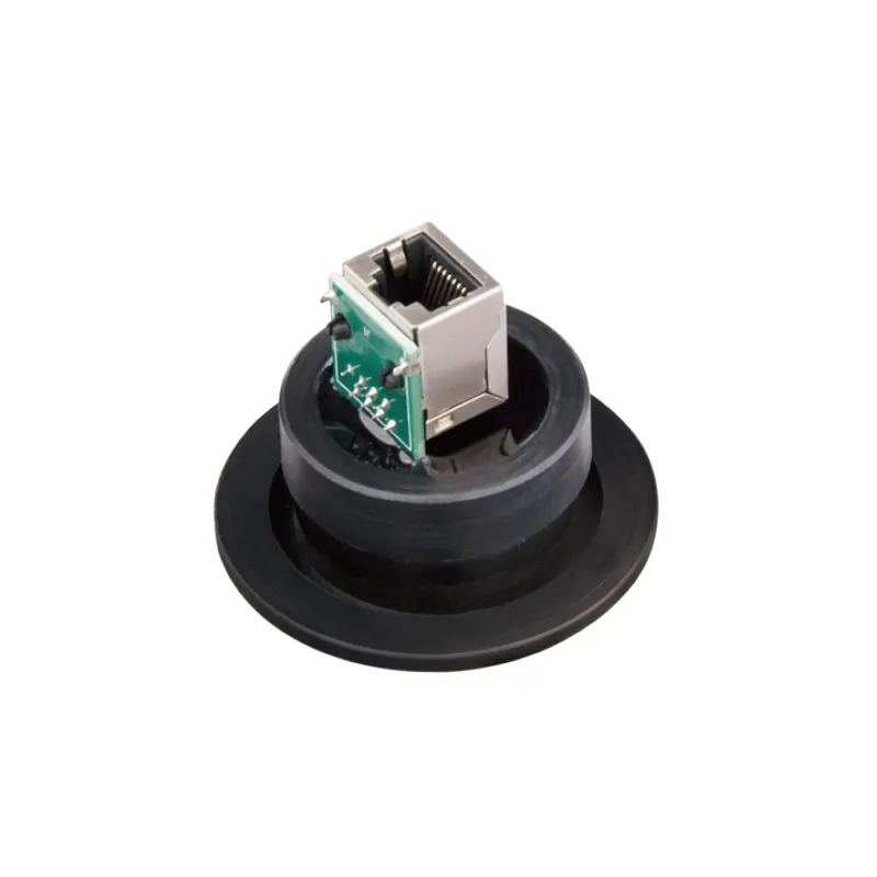
Feedthroughs are one example of a broader rule: every accessory that penetrates the enclosure should be selected for the service it will actually see, and the interaction between accessories should be checked rather than assumed. A feedthrough, a solvent-adsorption unit and an additional analyser port all consume ports and all add joints to be verified.
Indicators that are often confused
Most troubleshooting errors come from comparing numbers that describe different things. The table below separates the quantities that are routinely mixed up in discussion of purifying glove boxes.
| Quantity | What it describes | Typical mistake |
|---|---|---|
| Oxygen and moisture concentration in the box | The current condition of the working atmosphere | Treating a single reading as a specification for all operating states |
| Leak rate of the enclosure | How much gas passes a seal under a defined pressure difference | Assuming a low leak rate means fast recovery |
| Transfer chamber vacuum | The pressure reached in the antechamber during its cycle | Confusing it with the box working pressure or with pump ultimate vacuum |
| Pump ultimate vacuum | A property of the pump, measured under defined conditions | Reading it as the vacuum the chamber will reach in service |
| Analyser resolution and accuracy | Display increment versus correctness of the value | Taking resolution as evidence of precision |
Configuration checklist before the order is placed
Recovery behaviour is largely decided at specification, not at commissioning. The questions below are worth answering in writing, because each one changes the layout, the port list or the operating procedure.
- Transfer duty: how many transfers per day, of what size, and whether the load is a sealed container, an open dish or a powder. Specify a vacuum-capable transfer chamber if dilution-only transfer would put the atmosphere outside specification.
- Station use: whether the two workstations will be used simultaneously by different people, and whether one must remain undisturbed while the other is loaded.
- Site access: the door widths, lift capacity and corridor turns on the route to the room, which determine whether split-type construction is required and how the sections will be joined.
- Materials: sample chemistry, solvents used inside the box, and whether a solvent-adsorption stage is needed in addition to water and oxygen removal — it is an addition, never a substitute.
- Ports and penetrations: the number and type of feedthroughs, the services already assigned to each port, and the connectors on the instruments that will be used.
- Monitoring: how many measurement points, where they sit relative to supply and return, and the range, resolution and calibration arrangement of each sensor.
- Process environment: whether the work also requires particulate filtration, and the recognition that HEPA filtration addresses particles and not water, oxygen or solvent vapour.
What to send the supplier
A useful enquiry describes the process rather than asking for a model number. Include the materials to be handled and their sensitivity, the number of operators and stations in use at once, the transfer routine and load sizes, the target atmosphere and how it will be verified, the instruments that need connections through the wall, the solvents involved, and the access route into the building. Ask explicitly which figures are guaranteed for the configuration being quoted and under which conditions they apply, and ask for the recommended leak-check interval and the procedure for the joints between sections.
When a recovery problem appears later, the same information shortens the diagnosis: a record of when the curve changed, what was transferred immediately before, whether the idle baseline moved, and whether the analyser was calibrated in the same period will usually identify which of the three contributions — carried-in air, outgassing or continuous ingress — has changed. That is a more productive starting point than replacing purification material on suspicion.
