
In an inert-atmosphere laboratory, the glove box is often described in terms of its purification system, antechamber, and gloves. The electrical boundary is discussed less often, even though every sensor, small heater, electrochemical cell, or test fixture inside the enclosure eventually needs a connection to the outside. Passing a cable through a door seal or a glove port is a temporary habit with permanent consequences: it can damage the seal, strain the cable, compromise the atmosphere, and make measurements difficult to repeat. A dedicated feedthrough turns that ad hoc crossing into a defined interface.
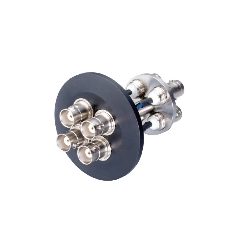
The KF40 BNC Feedthrough Connector is an accessory in that category. Its name identifies two important interfaces—a KF40 flange and a BNC connection—but those two pieces of information are not a complete specification. This article explains where such a feedthrough fits in a glove box system, how it affects sealing and signal quality, and which points should be confirmed before purchase. The aim is not to declare that one accessory suits every enclosure. It is to help engineers ask better questions about the boundary between a controlled atmosphere and the instruments that serve it.
Why a dedicated electrical feedthrough belongs in the atmosphere plan
A glove box is a system of controlled penetrations. The gloves allow hands in, the antechamber allows samples in, the gas circuit allows the atmosphere to be managed, and the feedthrough allows signals out. Each penetration has to balance access against containment. A cable laid across a door gasket is an uncontrolled penetration: the gasket may not seat uniformly, the cable jacket may be pinched, and the user may need to open the door more often than necessary. A cable pushed through a glove port is worse in some ways, because it interferes with hand movement and can abrade both glove and cable.
A fixed feedthrough does not remove the need for careful atmosphere control. It simply moves the electrical crossing to a place designed for it. The connection becomes repeatable, labelable, and easier to leak-check. Internal wiring can be routed once, with a service loop, instead of being re-run for every experiment. External instrumentation can remain connected while the box is closed. These are workflow benefits rather than atmosphere-performance claims, and they are the main reason to plan feedthroughs before the enclosure is crowded.
What the accessory does—and what it does not do
A feedthrough is an interface, not a purification device. It does not remove oxygen or water, generate inert gas, measure contamination, or replace a solvent adsorber. It does not turn a vacuum glove box into a continuously purified glove box, and it does not make an enclosure suitable for a process it was not designed to contain. Its job is narrower: carry electrical signals through the enclosure wall while preserving the wall's function as a boundary.
That narrow job still has several parts. The connector has to mate with the internal and external cables, the flange has to seal against the enclosure port, the conductor and insulator have to survive the local atmosphere, and the assembly has to tolerate the way the box is used. A part that works on a bench-top vacuum chamber may not be the best choice for a glove box that is opened daily, cleaned with solvents, or cycled between vacuum and inert gas. The application, not the product name alone, determines suitability.
How a KF40 BNC feedthrough fits into a glove box system
The product name points to a flange interface and an electrical connector. KF40 identifies a flange family used on vacuum and controlled-atmosphere equipment; BNC identifies a coaxial, bayonet-locking connector family. The combination is intended to let a BNC cable connection pass through a KF40 port. That description is useful, but it is still a starting point. The user needs to know whether the port on the enclosure is a mating KF40 port, whether the required clamp and seal are supplied or separately specified, and whether the feedthrough's electrical and vacuum characteristics fit the task.
In a typical signal path, a sensor or test fixture inside the box connects to an internal cable, the internal cable terminates at the BNC side of the feedthrough, the feedthrough passes through the enclosure wall, and an external cable carries the signal to a data logger, controller, or instrument. The shield and ground path are part of that circuit. So is the mechanical support: a connector should not be used as a cable anchor. If the internal cable hangs from the feedthrough, or the external cable pulls sideways on it, the connection may become intermittent and the seal may be stressed.
Flange, seal, and port: the mechanical side
A KF-style connection is a clamped flange arrangement that relies on a mating counterflange, a sealing element, and a clamp or retaining method. The exact components depend on the product and the port. Before ordering, confirm the flange size and type, the mating hardware, the seal material, the required surface condition, and the available clearance around the port. A feedthrough that fits physically may still be wrong for the enclosure if the seal material is incompatible with the process atmosphere or the cleaning agents.
The enclosure side matters just as much. If the glove box already has a suitable KF40 port, the installation question is mainly about sealing, clearance, and electrical integration. If it does not, do not treat the enclosure wall as a generic sheet to be drilled. A glove box may be a pressure vessel, a vacuum chamber, or a precisely built recirculating enclosure. Adding a port can affect strength, leak tightness, and warranty. Ask the enclosure supplier about a factory-supported port or a qualified modification before any cutting is considered.
BNC: a connector family, not a complete signal specification
BNC connectors are widely used for low-voltage signals because they are compact, familiar, and have a bayonet coupling that seats with a quarter turn. That does not mean every BNC feedthrough is interchangeable. The purchaser should confirm the number of connections, the impedance and cable type if relevant, the voltage and current limits, the frequency range, the shield-to-flange relationship, and the mating cable or adapter. A BNC shell may be connected to the flange, isolated from it, or arranged in another way; the difference matters for grounding and noise.
The connector also has to suit the signal. A low-level analog sensor, a digital communication line, and a pulsed measurement can place different demands on shielding, impedance, and crosstalk. BNC may be a good fit for one and a poor fit for another. It is not a universal power connector, and it should not be assumed to be rated for mains voltage, high current, high voltage, or safety interlocks unless the product documentation explicitly says so. If the signal is not clearly low-voltage and low-energy, the electrical rating should be confirmed in writing before the part is connected to anything.
Electrical compatibility: match the connector to the signal, not just the hole
A common purchasing error is to choose a feedthrough by flange alone. The flange answers “will it mount?” It does not answer “will the measurement remain clean?” A BNC feedthrough can be mechanically correct and still cause trouble if its shield path creates a ground loop, if its insulator is incompatible with the atmosphere, or if the cable and connector are asked to carry a signal outside their intended range.
Start with a signal list. For each channel, record whether it is analog or digital, its expected voltage and current, its bandwidth or frequency content, its source impedance, and whether it is single-ended or differential. Then record the cable type and the instrument's input configuration. This information lets the supplier confirm whether the feedthrough is appropriate. It also reveals whether one feedthrough is enough. A project that begins with one sensor often grows to include a second probe, a reference electrode, a thermocouple, or a synchronization line. Leaving spare capacity in the port plan is usually easier than reopening the question later.
Shield and ground questions to settle before purchase
- Is the BNC shell connected to the flange, or is it isolated? The answer affects grounding and noise.
- Does the enclosure serve as the system ground, and where does the data logger ground connect?
- Will the shield be continuous from the sensor to the instrument, or is a break intended?
- Are multiple feedthroughs likely to create parallel ground paths?
- Does the installation need a dedicated ground stud or bonding point separate from the signal shield?
These questions are not abstract. In a metal enclosure, a shield that contacts the flange at one point and the instrument chassis at another can form a loop. The result may be mains-frequency noise, baseline drift, or unexplained offsets. The cure is not always a different feedthrough; sometimes it is a changed grounding scheme, an isolated connector, or a different cable route. The point is to decide the scheme deliberately, not to discover it after the experiment has begun.
Noise, cable routing, and the rest of the system
A feedthrough is a short section of the signal path, but it sits at a boundary where cable routing changes. Inside the box, cables may run near heaters, motors, or lamps. Outside, they may run beside pump controllers and power supplies. A shielded cable that is perfect on the bench can pick up noise when it is draped across a power cable. Keep signal and power routes separated where practical, provide strain relief, and avoid tight bends at the connector. If a reading is noisy, test the cable and instrument first, then inspect the shield and ground path. Do not assume the feedthrough is faulty without evidence.
Sealing, vacuum, and atmosphere compatibility
Every feedthrough is a potential leak path. There is a seal at the flange and usually a sealed or insulating path around the conductor. The quality of the installation therefore matters as much as the part. The mating surfaces should be clean and undamaged, the correct seal should be used, and the clamp should be fitted according to the supplier's instructions. A seal that is twisted, contaminated, or compressed unevenly may pass a quick check and fail later. After installation, the enclosure's leak behavior should be checked using the method appropriate to the system.
“Vacuum” and “inert atmosphere” are not interchangeable requirements. A continuously purified glove box often operates near ambient pressure, with a slight positive or negative differential depending on the design, while a vacuum glove box is exposed to pressure changes and pump-down cycles. A feedthrough that is acceptable for one regime is not automatically acceptable for the other. The product documentation should state the intended pressure or vacuum conditions, the allowable differential, and any installation orientation or support requirements. If those details are not available, they should be requested before the part is used in a pressure-critical location.
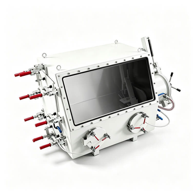
A stainless steel vacuum glove box such as the GBV-1 illustrates the background clearly. Its controlled environment depends on a sealed chamber, vacuum and inert-gas exchange, and careful management of every penetration. That does not establish that a particular KF40 BNC feedthrough is compatible with the GBV-1, nor does it mean the GBV-1 has a KF40 port as standard. The relevant point is architectural: a vacuum-capable enclosure places different demands on a feedthrough than a simple acrylic glove box or a continuously purged stainless steel box. Confirm the enclosure interface and the feedthrough rating as a pair.
Material compatibility deserves the same attention. The internal side of the feedthrough may be exposed to the process atmosphere, solvent vapors, cleaning agents, or trace reactive species. The insulator, seal, and metal surfaces all matter. A connector that is electrically correct can still be a poor choice if its polymer parts absorb solvent, degrade, or outgas. Outgassing is especially relevant in a closed-loop glove box, where a small amount of contamination can affect trace water or oxygen readings. Ask for the materials of construction and cleaning guidance, and do not assume that a generic BNC connector is suitable for every chemistry.
Installation and daily use: plan the port, protect the signal
The best time to plan a feedthrough is before the glove box is configured. Choose a location that leaves room for the internal cable, the external mating connector, and the user's hands. Avoid placing it where it will interfere with glove ports, the antechamber door, the viewing window, or a moving fixture. Consider whether the cable will hang vertically, whether a right-angle adapter is needed, and whether the connector can be capped when unused. A feedthrough that is awkward to reach may be left connected when it should be isolated.
On the inside, provide a service loop so that the cable is not tensioned when a sensor is moved. Support the cable with a clamp or tie point that does not load the connector. On the outside, provide strain relief so that the weight of the cable is carried by a support rather than by the BNC coupling. Use the correct mating cable, insert and lock the bayonet fully, and avoid twisting the cable at the connector body. If the feedthrough has a protective cap, use it when the port is open to the room; an open port is both a contamination path and an injury or damage risk.
Maintenance and troubleshooting without jumping to conclusions
Inspect the accessible parts periodically: the flange surfaces, the seal, the connector shell, and the contacts. Look for corrosion, cracks, discoloration, or debris. Clean only with methods and agents that the supplier permits; a solvent that is harmless to stainless steel may attack an insulator or a seal. If a signal becomes intermittent, test the external cable, the internal cable, and the instrument separately. If the atmosphere recovery slows after a feedthrough is installed, check the seal and the mating flange before blaming the purification system. If a reading is noisy, check the ground scheme and cable routing. The feedthrough is one element in a chain, and the diagnosis should follow the chain.
Do not use the feedthrough as a feed for anything it was not specified to carry. A BNC connection may look convenient, but convenience is not an electrical rating. Do not run mains power, high voltage, high current, or safety interlocks through an accessory unless the product documentation explicitly covers that use and the installation is designed for it. If the application requires a different signal type, the correct answer may be a different feedthrough configuration rather than an adapter that pushes the part beyond its intended role.
Configuration and compatibility checklist
The following checklist is a practical way to organize the questions. It does not replace the product datasheet or the enclosure manual. It simply puts the decisions in the order in which they affect the system.
| Item to confirm | Why it matters | Information to provide or request |
|---|---|---|
| Enclosure interface | A feedthrough is only useful if the port and mating hardware are correct. | Enclosure model, port type, flange size, mating clamp and seal, available clearance. |
| Signal type | BNC is a connector family, not a guarantee of suitability for every signal. | Analog or digital, voltage, current, frequency, source impedance, single-ended or differential. |
| Connector count and configuration | Future channels are easier to plan than to retrofit. | Number of BNC connections required now, spare capacity, labeling scheme. |
| Shield and ground | Ground loops and shield continuity affect noise and safety. | Whether the shell is isolated or connected to the flange, instrument ground scheme, bonding points. |
| Pressure or vacuum regime | Continuous purging and vacuum cycling place different demands on the seal and body. | Operating pressure, pressure cycles, differential, leak-check method, installation orientation. |
| Atmosphere and materials | Insulators and seals may be affected by solvents, oxygen, or cleaning agents. | Process gases, solvent vapors, cleaning agents, temperature, required materials of construction. |
| Cable and strain relief | Mechanical load can damage the connector and stress the seal. | Cable type, bend radius, support method, internal service loop, external cable weight. |
| Electrical ratings | Unspecified ratings should not be inferred from the connector shape. | Voltage, current, frequency, insulation, and any applicable safety requirements in writing. |
| Documentation | Installation and verification need a traceable basis. | Dimensional drawing, materials, rating information, cleaning guidance, installation instructions. |
| Spare and future use | Research setups change, and unused ports can be capped. | Expected channel growth, spare feedthrough or spare port, labeling and isolation plan. |
When the KF40 BNC feedthrough is the right choice—and when it is not
The accessory is a sensible candidate when the enclosure has a compatible KF40 interface, the signals are low-voltage and suited to BNC cabling, the grounding scheme can be defined, and the user has confirmed the pressure, atmosphere, and material requirements. It is also a good fit when the workflow needs a repeatable connection that can be disconnected without disturbing a door seal or a glove. In those cases, the feedthrough is a small but useful piece of infrastructure: it protects the atmosphere boundary and makes the electrical setup easier to document.
It is not the right choice merely because it is available. If the enclosure has no suitable port, if the signal is mains power or high energy, if the process atmosphere attacks the available materials, if the pressure regime exceeds the confirmed rating, or if the installation would place mechanical load on the connector, a different approach is needed. The correct response may be a factory-engineered port, a different feedthrough style, a separate instrument enclosure, or a redesign of the measurement so that the sensitive electronics remain outside the glove box. Those are system decisions, not accessory decisions.
The KF40 BNC feedthrough product page is the place to start for the specific part, but the purchasing decision should include the enclosure manual and the instrument requirements. A feedthrough is small enough to be treated as an afterthought and important enough to affect leak tightness, noise, and daily workflow. Treating it as part of the atmosphere plan is more reliable than discovering its limits after the box has been commissioned.
What to send the supplier before ordering
A useful inquiry is specific about the system, not just the part name. Provide the enclosure model and a description of the port, including whether it is a factory port or a proposed modification. State whether the box is continuously purged, vacuum-operated, or used for both. List the signals, their voltage and current levels, their frequency content, and the cable types. Describe the grounding scheme and say whether shield isolation is required. State the process atmosphere, cleaning agents, and temperature. Include a sketch or photo of the available space if clearance is tight.
Ask for the dimensional drawing, materials of construction, electrical ratings, pressure or vacuum information, seal specification, and installation instructions. Ask whether the mating clamp, seal, and cable-side connector are included or must be ordered separately. Ask whether the feedthrough is compatible with the specific enclosure interface, and ask what verification is recommended after installation. Finally, ask what information the supplier needs in order to confirm suitability rather than simply supply a part. A clear answer to that last question is often more valuable than a long list of generic specifications.
The atmosphere inside a glove box is only as reliable as the boundaries around it. A KF40 BNC feedthrough is a modest accessory, but it sits at exactly that boundary. Selecting it on the basis of the flange alone leaves the electrical, sealing, and material questions unanswered. Selecting it as part of a defined signal and atmosphere plan gives the user a connection that can be checked, maintained, and trusted within its stated limits.
