
Why a signal entry point deserves the same attention as the purifier
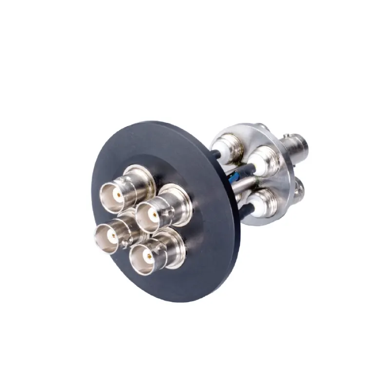
A glove box with a gas purification system is, functionally, a closed loop. The working volume, the circulation path, the purification column, and the analyzers that report oxygen and water content all cooperate to hold the process atmosphere inside a defined working range. The loop is only as tight as its weakest boundary, and the boundaries are not limited to the gloves and the main door. Every cable that must reach a sensor, a test cell, a probe, a heater, or a camera inside the box is a deliberate penetration of that boundary. A KF40 BNC feedthrough exists to make one such penetration permanent, sealed, and repeatable instead of improvised.
The approach most laboratories try first is to run the coaxial cable through the antechamber, across the main door seal, or alongside a glove. It works once. Then the antechamber is cycled again, the door is opened, a glove is changed, and the cable has to be re-routed. Each of those events brings the inner volume into contact with room air and forces the purification column to remove the moisture and oxygen that enters with it. In a box used for one experiment at a time, that is a manageable inconvenience. In a system organized around parallel work, the cost is shared, because one gas circuit and one controlled atmosphere serve every working position.
Reading the product name: what a KF40 BNC feedthrough tells you and what it does not
The name of this accessory is a compressed specification. It identifies the mechanical interface at one end, the electrical interface at the other, and the fact that the two are joined through a sealed body. It does not give the ratings, the materials, or the grounding scheme, and those are precisely the details that decide whether the part fits an experiment.
The flange side: KF40 is a flange family, not a universal port
KF, also written ISO-KF or NW, is a nominal-bore flange family. It seals with a centering ring that carries an O-ring, compressed by a clamping ring. The number in the designation refers to the nominal bore of the flange, not to the outside diameter of the assembled joint, and the series is not interchangeable with CF (ConFlat) flanges or with other ISO series. If the port you intend to use is a KF25 blank, a CF port, or a threaded port, a KF40 body will not mount without an adapter, and an adapter adds another seal, another volume, and another item to leak-check. Identify the port by series and nominal size before ordering, and confirm that it is genuinely spare: a port already carrying a pressure gauge, a probe, or a gas line is not available.
The signal side: BNC describes the connector, not the measurement
BNC is a bayonet-locking coaxial connector, widely used in laboratory instrumentation because it mates quickly and maintains a continuous shield when terminated correctly. It is generally a low-voltage, low-power signal interface. Coaxial lines are built around a characteristic impedance, and both 50 ohm and 75 ohm variants are in circulation, so the impedance should be matched to the rest of the signal chain when the measurement is sensitive to reflections or cable loss, as in high-frequency impedance spectroscopy. What the connector name does not tell you is whether the shield is isolated from the flange or bonded to it. That single detail determines whether the feedthrough introduces a ground loop into your setup or avoids one.
The body: dielectric, seal, and the conductor path between them
Between the two interfaces sits the part that does the actual work: a conductor passing through an insulating body that is sealed to the flange. The construction may be ceramic-to-metal, glass-to-metal, or polymer-sealed. That choice governs the usable temperature range, the outgassing behavior in a dry or evacuated environment, and the cleaning methods the part tolerates. None of it can be inferred from a product listing title; it has to come from a data sheet or from the supplier.
Where the feedthrough sits inside a purified glove box system
It helps to think of the box in layers. The innermost layer is the working volume and whatever the process requires: a cell, a sample holder, a fixture. The next layer is the atmosphere itself, meaning the circulating working gas, the purification column that removes water and oxygen, and the control logic that decides when the column is regenerated. The outermost layer is the interface with the outside world: the gloves, the antechamber, the gas panel, the analyzers, and the instrument connections. A feedthrough belongs to that outer layer. It is not part of the purification function and does not improve the atmosphere. Its job is to preserve the atmosphere boundary while a measurement crosses it.
What crosses in practice? Temperature sensors and thermocouples, electrochemical or impedance measurement leads, photodetector and spectrometer signals, pressure and flow sensor outputs, and low-current control lines. Each has a different noise sensitivity and a different grounding requirement, and each is a candidate for a sealed coaxial penetration rather than a bare wire. A bare wire pushed through a drilled hole or, worse, laid across a door gasket, is a classic source of slow and unexplained drift in water and oxygen readings, because the leak is small, distributed, and difficult to locate once the box is closed.
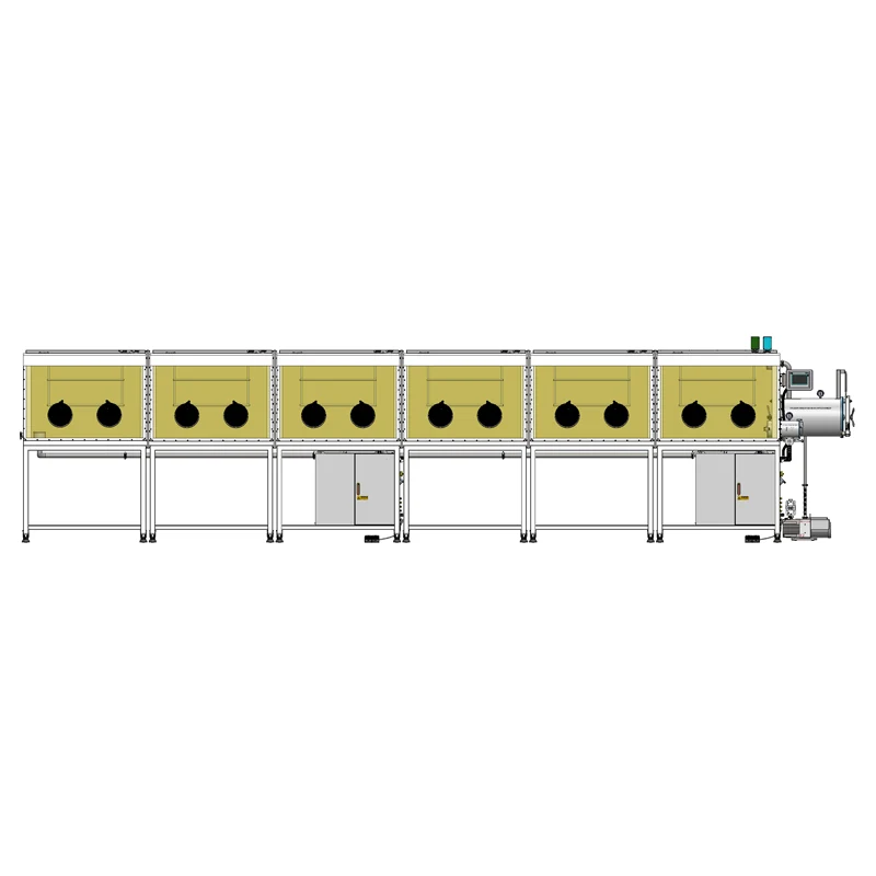
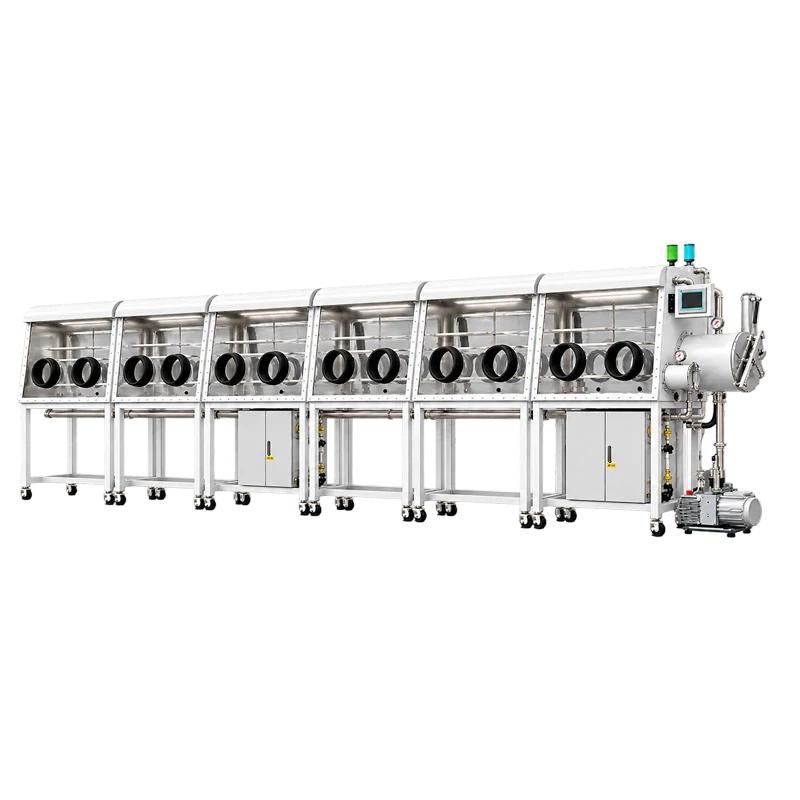
This is also why the accessory should be considered in the plural. A purifier box built with twelve stations, double-sided access, and a split configuration is organized around more than one working position and often more than one operator. The number of instrument connections tends to grow with the number of experiments, and a design that treats each penetration as an isolated decision produces an inconsistent system, with some ports sealed correctly and others improvised. Choosing one or two standard feedthrough types and repeating them across the box is easier to maintain than solving each connection separately. The twelve-station double-sided split-type glove box with gas purification system is one example of a platform where that discipline pays off, because a shared gas circuit makes every penetration a shared risk.
What the accessory is not responsible for
The most useful way to evaluate a feedthrough is to separate what it does from what it is assumed to do. A correctly installed KF40 BNC feedthrough provides a sealed mechanical penetration and a continuous coaxial path. It does not purify gas, it does not filter particles, and it does not repair a leak elsewhere in the system.
| Function | What the feedthrough does | What it does not do |
|---|---|---|
| Atmosphere boundary | Provides one sealed penetration through a compatible flange port | Does not guarantee the overall leak rate of the box; other ports, gloves, and doors still have to be checked |
| Signal path | Carries a coaxial signal from inside to outside with a continuous shield | Does not amplify, filter, or condition the signal, and does not correct a poor grounding scheme |
| Gas purification | Nothing | Does not remove water, oxygen, or solvent vapor from the atmosphere |
| Particle control | Nothing | Does not replace HEPA filtration or any particulate control device |
| Compatibility | Fits ports of the same flange series and nominal size | Does not fit every glove box port; the flange series and size must be verified first |
Selection criteria: what to confirm before ordering
Because the product name carries only the flange and connector designations, the practical work of selection is a short list of technical questions. The following six items cover most of the decisions that later turn into problems, either as leaks or as noise.
Flange and port compatibility
Confirm the flange series and nominal size of the port, its location on the box (wall, antechamber, or gas circuit), and the radial clearance available for the clamping ring. A KF40 assembly occupies more space than the bore suggests, because the clamp has to be turned and seated. Also confirm what is included: a centering ring, a clamp, and a blanking plate are separate items in many catalogs, and a missing centering ring is a common reason a new feedthrough is installed without a proper seal. If an adapter is required, treat the adapter as part of the sealing system and leak-check it with the same method used for the feedthrough itself.
Electrical parameters and impedance
Check the expected voltage, current, and frequency of the signal, and match the connector and cable impedance to the instrument. Confirm the connector gender on both faces, since the inside-facing and outside-facing ends are not always the same, and confirm the cable type used inside the box. For microvolt-level measurements, the connector choice and the shield treatment usually matter more than the flange size. If the connection is intended for heater power, a solenoid, or a high-voltage bias, a signal-grade coaxial feedthrough is the wrong component; specify a power or high-voltage feedthrough rated for that duty instead.
Leak tightness, pressure side, and outgassing
Ask which side of the part is rated for vacuum, and what leak rate the supplier specifies. In a purifier glove box the differential pressure across the wall is modest, but a vacuum antechamber and a vacuum oven inside the box can subject the same fitting to a much larger gradient in the other direction. Outgassing matters in a different way: a dielectric or elastomer that releases volatiles inside the box adds to what the purification column has to remove, which is a slow and easily misattributed load. The part should be specified for the intended temperature and atmosphere, not for room air only.
Materials and chemical compatibility
Ask for the list of materials in contact with the box atmosphere: the flange body, the dielectric, the O-ring, and the conductor plating. The usual fault line is the O-ring, where the choice among fluoroelastomer, silicone, and perfluoroelastomer decides how the seal behaves under solvent vapor or elevated temperature. If the work involves lithium metal, strong solvents, or acid vapors, check compatibility for each material rather than assuming the fitting is inert. The cleaning method follows from the same answer, because a polymer-sealed part generally does not tolerate the same procedure as a ceramic-to-metal part.
Physical envelope and cable routing
Measure the overall length and how far the body and connector extend into the working volume, particularly in a double-sided box where the operator space is bounded on both faces. Inside the box, cables need strain relief so that movement of a probe or a sample holder does not load the feedthrough body; the seal should never be the item that absorbs a bending force. Outside the box, leave room for the mating cable minimum bend radius. These are dimensional questions, and a drawing is the only reliable answer.
Grounding and shielding strategy
Decide before ordering whether the shield should be grounded inside the box, outside the box, or at a single point, and whether the feedthrough body itself should be isolated from the box. When a box and an instrument share a building ground, connecting the cable shield at both ends creates a loop that shows up as line-frequency hum or as noise that changes when the operator touches the frame. A floating-shield feedthrough, or an insulating flange adapter, is the usual remedy. The point is that this decision is a property of the installed part, not something that can be corrected later with software.
Interpreting common symptoms
When something goes wrong with an instrument connection, the feedthrough is only one of several candidates. The value of understanding the mechanism is that it turns guesswork into a short list.
Noise that appears or changes when the box is touched
This pattern usually points to a grounding problem rather than to the sealing of the feedthrough. If the shield is bonded to the flange at the box and also grounded at the instrument, the enclosure and the instrument form a loop. Single-point grounding and, where appropriate, an isolated shield path are the standard fixes. A feedthrough whose shield is deliberately isolated from the flange is the component that makes such a scheme possible.
Slow recovery of water and oxygen readings after a transfer
Slow recovery after the antechamber has been cycled is most often caused by the volume of air introduced, by glove porosity, or by material that was brought in with the sample. A feedthrough is a permanent penetration and belongs on the leak-check list, but a small static seal is rarely the sole explanation for a large or repeated excursion. The reasonable approach is to establish a baseline recovery curve for routine transfers, and then investigate only what departs from it. Without that baseline, any fitting becomes a plausible suspect.
A connector that warms up or whose resistance changes
Temperature rise at a connector indicates that the current exceeds what the contact was designed to carry, or that the mating surfaces are not fully seated. Signal-grade coaxial connectors are not power connectors. If a heater, a motor, or a solenoid has been connected through a signal feedthrough, the correct response is to replace it with a power-rated penetration rather than to increase the cooling.
Discoloration, corrosion, or unexplained solvent readings
Material degradation at the fitting points toward a compatibility problem rather than an electrical one. An elastomer that swells in a solvent loses its sealing force slowly, and the effect appears as a gradual drift rather than an obvious leak. Reviewing the wetted materials against the actual chemistry in the box is the only way to resolve it.
Installation and verification sequence
Once the part has been selected, the installation itself follows a short, repeatable sequence. The steps below apply to any flange-mounted feedthrough, and they are worth standardizing across a multi-station box so that every penetration is documented the same way.
- Verify the port: series, nominal size, clearance, and the fact that the port is genuinely free.
- Inspect the flange faces and replace the O-ring; confirm that the O-ring material matches the chemistry in the box.
- Seat the centering ring, fit the clamp, and tighten evenly. Overtightening distorts the ring without improving the seal.
- Connect the cable inside the box with strain relief, so that no mechanical load reaches the feedthrough body.
- Leak-check the joint by the method your laboratory uses, such as an isolated pressure hold or a trace-gas check if that equipment is available.
- Record a baseline: analyzer readings with the instrument energized and with a known signal applied, so later changes can be compared against something.
- Document the grounding scheme and the cable type, and note it on the instrument map for the box.
What to give the supplier
A feedthrough order is easier to get right when the enquiry carries the application, not just the part number. The following information lets a supplier confirm compatibility instead of guessing at it.
- Glove box model or configuration, and the flange series and nominal size of the port to be used.
- Port location (box wall, antechamber, or gas circuit) and whether any vacuum operation is expected on either side.
- Signal type and range: voltage, current, frequency, and the characteristic impedance of the measurement line.
- Preferred shield grounding scheme, and whether an isolated body is required.
- Connector gender on the inside and outside faces, and the cable type used inside the box.
- Maximum operating temperature at the fitting.
- Chemicals, solvents, or reactive materials present in the box, and the intended cleaning method.
- Whether a centering ring and clamp are included, and whether a dimensional drawing and a leak-rate specification can be provided.
This last point is worth emphasizing. A supplier who can state the wetted materials, the leak-tightness specification, and the dimensional envelope has answered almost every question that a product listing cannot. Those three documents, rather than the model designation, are what make a feedthrough a documented part of the atmosphere system.
Treating penetration points as part of the atmosphere design
The KF40 BNC feedthrough connector is a small component with a narrow job: carry one coaxial signal through a flange port without opening the box. In a system that already includes a circulation loop, a purification column, and continuous monitoring, that job is not trivial. Each instrument connection is a place where the controlled atmosphere meets the uncontrolled room, and the quality of that junction determines how much work the purification system has to do and how much confidence the measurements deserve.
The practical conclusion is a design habit rather than a product recommendation. Decide on the flange standard and the connector types early, before the instrument list grows; keep the number of penetration types small; check each joint for leaks at installation rather than after a problem appears; and record the grounding scheme alongside the cable details. A glove box with twelve stations, access from both sides, and a split layout will accumulate connections quickly, and the atmosphere it maintains will reflect the weakest of them.
Finally, keep the boundaries clear when specifying. A feedthrough seals a penetration, but it does not purify, filter, or measure. The analyzers measure the atmosphere, the purification column cleans it, and the gloves and the antechamber separate it from the room. A feedthrough simply keeps a signal path from undermining all three.
