
A KF vacuum clamp is a hinged metal ring, tightened with a screw or a wing nut, that pulls two KF flange faces together so the elastomer O-ring held between them is compressed into a vacuum-tight joint. On a glove box installation the clamp belongs to the plumbing rather than to the enclosure: it sits at the joints of the vacuum manifold, the antechamber evacuation line, the vent and refill lines, and any gas path that has to be opened for service. It solves a narrow, practical problem — making a demountable joint dependable, leak-tight while it is closed and separable when a pump, valve or section of line has to be replaced.
That definition already sets a boundary. A clamp is a fastener. It does not seal on its own, it does not control flow, it does not filter particles, and it does not remove moisture or oxygen from the working gas. Those duties belong to the O-ring, the valve, the filter and the purification system respectively. Keeping the clamp's role clear is what stops a specification discussion from drifting into claims the hardware cannot support.
What a KF vacuum clamp contributes to a system
Every demountable joint in a vacuum or gas line has to satisfy two opposing demands: it must be tight enough that the line holds its intended vacuum or pressure, and loose enough that it can be taken apart. Flange systems resolve this by splitting the work. The flange faces provide flat, machined mating surfaces. The centring ring aligns the two bores and carries the elastomer seal. The clamp supplies the force that compresses the seal.
Because the clamp only supplies force, its quality shows up as consistency: load spread evenly around the circumference, no point loading that distorts a flange face, and enough mechanical strength that the closing action can be repeated many times without the thread or the hinge giving way. A clamp that is too light will flex under tension; one whose screw is worn will not reach the same compression twice; one made for a different nominal size will not close around the flange at all.
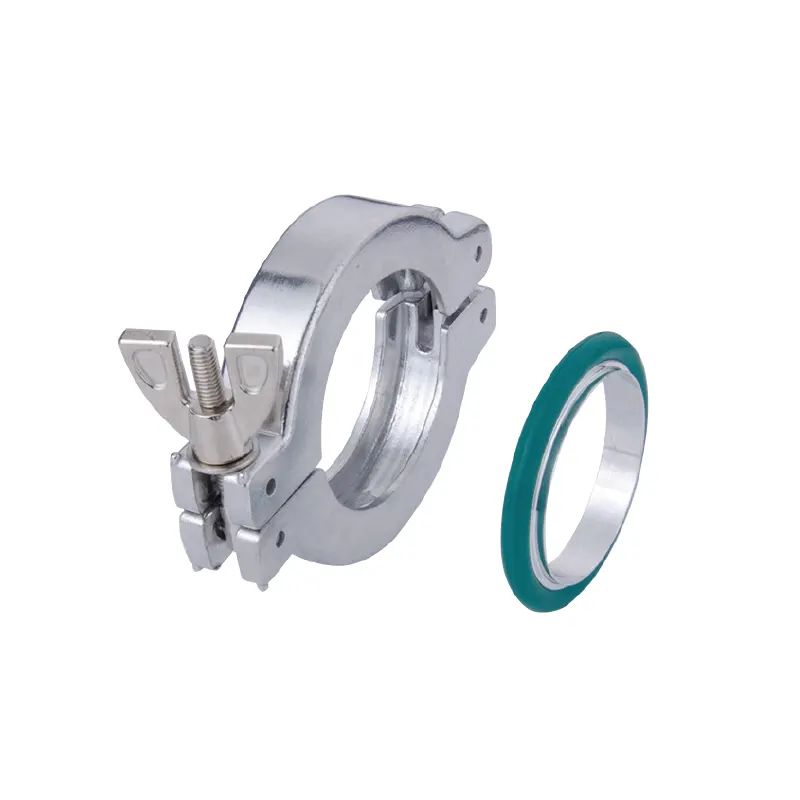
How the joint works, from clamping force to leak-tight seal
Three parts, three responsibilities
A KF joint is not a single component. It is an assembly of a flange face on each side, a centring ring with an elastomer seal, and the clamp that holds them together. The flange faces set the geometry and the surface quality. The centring ring keeps the bore aligned so the gas or vacuum path is not offset, and it holds the O-ring in a defined position. The clamp applies axial compression.
This division of labour matters when a joint leaks. Replacing a clamp will not repair a scored flange face, a swollen or hardened O-ring, or a centring ring that was never fitted. If a leak appears, the sensible order of checks is: is the seal present and correct, are the faces clean and undamaged, are the two flanges concentric and of the same nominal size — and only then is the clamp itself a suspect.
What tightening actually does
Tightening the clamp converts a small rotary input into an axial load. The seal deforms against the flange faces and into the joint gap, closing the microscopic channels that would otherwise let gas pass. The practical target is a uniform, moderate compression around the circumference: enough to close the joint, not so much that the elastomer is crushed, extruded or cut, and not so much that the flange faces are pulled out of parallel.
Two habits make the result reproducible. First, bring the clamp up to contact by hand and then tighten in a controlled way instead of forcing it. Second, re-check the joint after the line has been evacuated, pressurised or thermally cycled, because the assembly settles. A wing-nut clamp is convenient here: it invites a consistent hand-tight action rather than an over-torqued one, which is usually the right direction for an elastomer-sealed joint.
When a clamped joint starts to leak
Elastomer-sealed joints fail in a small number of recognisable ways. The seal can take a permanent compression set and stop recovering, which appears as a leak after a long period at temperature or after many cycles. The O-ring can be attacked by a solvent vapour or a reactive gas, swelling or hardening in the process. The flange faces can be scratched by a slipped tool. The clamp itself can be bent by misuse, or its screw thread can wear until it no longer holds tension. A joint can also be disturbed mechanically — a line resting its weight on the clamp, or pump vibration travelling along rigid pipe — until the load around the circumference becomes uneven. Each case has a different remedy, and only the last two involve the clamp as the failed part.
Where KF joints appear on a glove box installation
Clamped KF joints are common wherever a line has to be assembled, serviced or reconfigured. On a glove box installation the typical locations include the evacuation line between an antechamber and its vacuum pump, the pump inlet itself, vent and refill lines that return the antechamber to working pressure, and the gas manifold that distributes working gas to the enclosure or to auxiliary equipment.
On a system with a purification loop, more of the gas path runs through rigid or semi-rigid plumbing: the circulation path between the box and the purification column, regeneration gas lines, and connections to analysers or sampling points. Each of those joints is a place where a clamp has to hold. A larger split-type installation such as the eight-station double-sided split-type glove box with gas purification system has longer routing between enclosure, antechamber and purification unit, and correspondingly more joints to inspect. That is background rather than a compatibility claim: whether a particular clamp suits a particular port depends on the flange size and family on that port, not on the model name of the box.
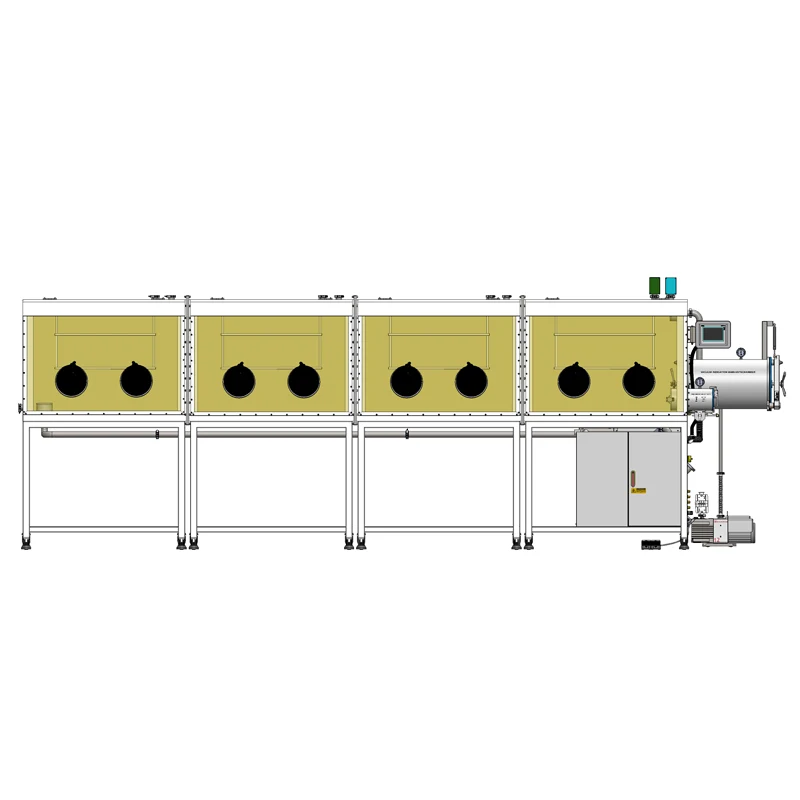
Which configurations matter when choosing
The TENCAN accessory range lists a single item for this job, the KF vacuum clamp, so the useful comparison is not between product names but between the joint conditions the clamp will meet. Four questions drive the choice.
Size and flange family
A clamp is only correct for the flange it was made for. KF joints are designated by a nominal size code, and the clamp, the centring ring and both flange faces must carry the same one. Pairing a clamp from one nominal size with a flange from another does not produce a weak joint; it produces a joint that cannot be assembled. It is also worth confirming that the port really is a KF-type joint, because metal-gasket and other high-vacuum flange families seal by a different principle and their hardware is not interchangeable.
Single-hinge clamp or multi-segment clamp
At small diameters, one hinged clamp with a single tightening point is enough: it opens over the flange pair and closes around it. At larger diameters that single point cannot spread load evenly around the circumference, so the clamp is built as a chain of segments with several hinges, which lets the ring follow the flange and tighten progressively. If a joint is difficult to reach, that difference in geometry matters more in practice than any figure on a data sheet, because the clamp has to be opened and closed in place.
Tightening method and access
Wing-nut and screw-tightened clamps both suit joints that are serviced by hand. The decision is usually made by access: how much swing room the handle needs, whether the joint sits inside a cabinet or behind a panel, and whether the operator can reach the full circumference. A clamp that can only be tightened from one angle will eventually be under-tightened on the far side.
Material, environment and seal hardware
Material and finish decide how a clamp behaves in a given room: a humid or solvent-exposed area, a wash-down environment, or a line carrying a reactive gas. Equally important, the seal is not part of the clamp. The O-ring and the centring ring are separate items, and their elastomer sets chemical compatibility, temperature range and permeation behaviour. A clamp that is perfect in every mechanical respect will still leak if the seal behind it is the wrong material for the gas it sees. For the current TENCAN item, the KF vacuum clamp product page is the place to confirm the offered size and material before ordering; where a value is not stated, ask rather than assume.
Specifications to verify before ordering
| Item to verify | Why it decides fit |
|---|---|
| Flange nominal size and family | Clamp, centring ring and both flange faces must match; components from other flange families do not interchange. |
| Number of clamp segments | Larger bores need multi-point or segmented clamps to load the seal evenly around the circumference. |
| Tightening method and handle clearance | Determines whether the joint can actually be tightened properly in its installed position. |
| Clamp material and finish | Sets corrosion behaviour against the room atmosphere, cleaning agents and the gases in the line. |
| O-ring and centring ring specification | The seal provides leak-tightness; elastomer choice sets chemical and temperature compatibility. |
| Duty of the line | Vacuum only, venting, or positive pressure — elastomer-sealed joints have limited pressure capability. |
| Support and routing | Rigid pipe should be supported separately so its weight is not carried by the clamp. |
| Availability as a spare | Joints that are opened routinely benefit from replacement clamps and seals being kept on the shelf. |
Where a KF vacuum clamp is suitable, and its limits
Clamped joints suit demountable connections on the vacuum side of antechamber evacuation, pump inlet lines, vent and refill lines, dry gas manifolds, sampling lines and temporary test rigs. Situations where the joint is opened for maintenance, where components are swapped during development, or where a leak check has to be run on one section of line all favour a clamp over a permanent connection.
The limits are just as clear. A clamp is not a valve, so it cannot isolate a section of line while the system runs. It is not a substitute for a welded or metal-gasket joint where elastomer seals are excluded by the process, for example during high-temperature bake-out or where elastomer permeation is itself unacceptable. It is not intended to hold significant positive pressure, and it should not be used as a mechanical support. Nor does it improve the atmosphere inside the box: closing a joint correctly removes one leak path, but the water and oxygen levels in the working volume are set by the purification system, the leak-tightness of the whole enclosure and the materials passed through the antechamber. Finally, a clamp cannot compensate for a damaged flange face — if the mating surface is scored, new hardware alone will not restore the seal.
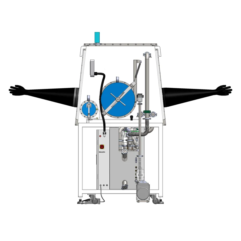
Selecting and integrating it into an existing system
- Identify the flange: read the size code on both flange faces and confirm which flange family the port belongs to.
- Confirm the seal hardware: centring ring and O-ring of the correct size and of an elastomer suited to the gas and temperature.
- Choose the clamp configuration: single hinge for small bores, segmented for larger ones, with a tightening method that suits the available access.
- Fit and tighten evenly, then test the joint. A rate-of-rise check on an evacuated antechamber or a leak check on the line section tells you more than the feel of the tool.
- Re-check after the first pressure or thermal cycle, and keep spare clamps and seals for joints that are opened often.
If any of these steps depends on data that is not published, confirm it with the supplier before the joint is assembled instead of assuming that parts of similar appearance will fit. A clamp is a low-cost item; a persistent leak in a purification-loop line, by contrast, shows up as a permanently higher load on the purifier and slower recovery after every transfer.
Frequently asked questions
Does a KF vacuum clamp include the O-ring and centring ring?
Usually not. Clamp, centring ring and O-ring are separate items and all three are needed for a complete joint, so check what the accessory listing actually contains before rebuilding a connection.
Can a KF vacuum clamp reduce the water and oxygen content inside the glove box?
No. It closes a mechanical joint. Water and oxygen removal is the job of the purification system and its columns; the clamp only helps ensure the vacuum and gas plumbing does not add an avoidable leak path.
Will any KF clamp fit any KF flange?
No. Two conditions have to match: the nominal size code and the flange family. A clamp one size away from the flange will not close around it, and hardware from a different flange family seals by a different principle.
Do I still need a proper clamp if the line is only used for venting?
Yes. Vent and refill lines have to be gas-tight in both directions, so they need a correctly sealed joint even though the clamp does not have to hold vacuum.
When should a clamp be replaced?
When its thread no longer holds tension, when it is visibly bent or its hinge is loose, or when it has been tightened against a damaged flange and deformed. Seals are replaced far more often than clamps — a persistent leak at a joint is more likely to be the O-ring, the centring ring or a damaged face than the clamp itself.
